MODULARM CORPORATION
61 MALL DRIVE, COMMACK, NY 11725 TEL 631-864-3860 ∙ FAX 631-864-3863
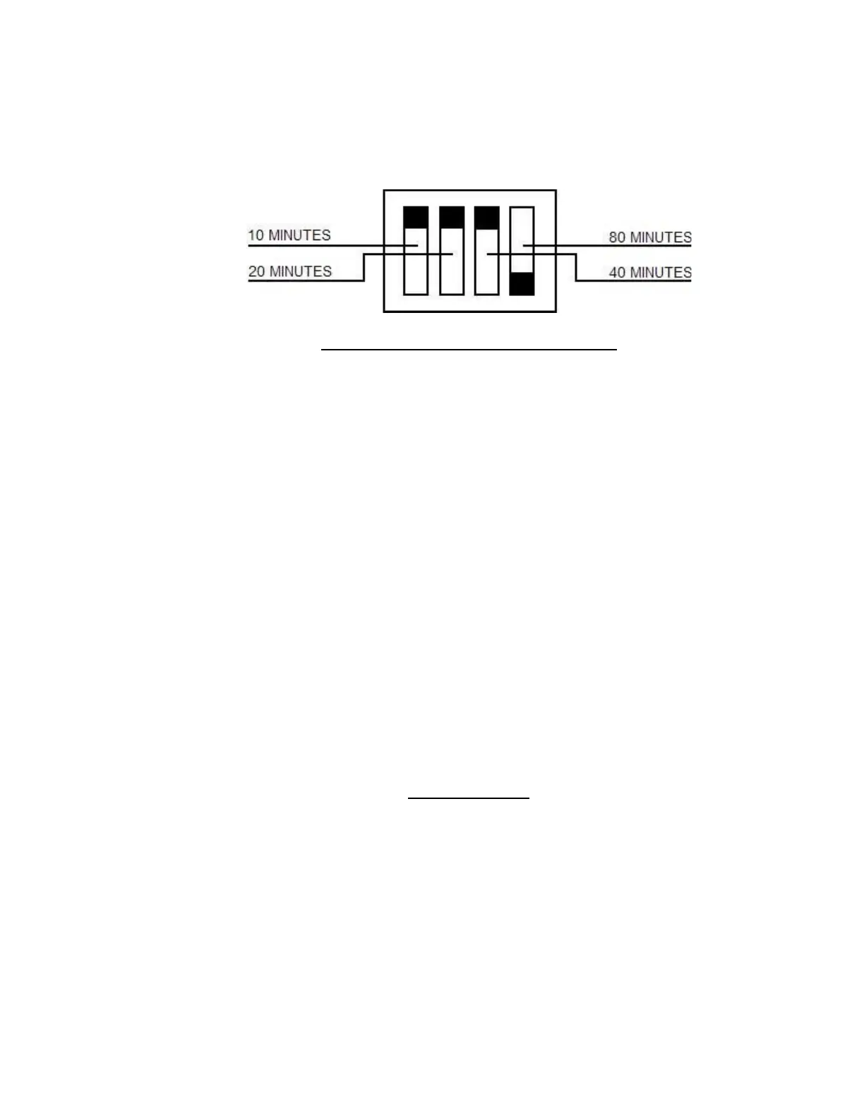
EXAMPLE: SET FOR 70 MINUTES DELAY
(BLACK SQUARE = PUSHED IN)
OPERATING SEQUENCE OF ALARM
Once properly installed and set up, virtually all user alarm functions are controlled by the ALARM
CONTROL SWITCH. This switch has two positions and for all monitored conditions there is only
one position of the ALARM CONTROL SWITCH where the alarm will be silent. The Model 75
was designed in this way so as t prevent the user from inadvertently leaving the ALARM
CONTROL SWITCH in the “wrong” position. WHEN THE ALARM IS SILENT, THE
CONDITION OF THE MONITORED BOX IS INDICATED BY THE STATUS LIGHTS.
NORMAL SEQUENCE OF OPERATION IS AS FOLLOWS:
GREEN LIGHT = SAFE CONDITION.
BLINKING RED LIGHT = ABNORMAL CONDITION. TIME DELAY INITIATED.
SOLID RED LIGHT = ALARM CONDITION. (HORN SOUNDS. RELAY ACTIVATED.
6 VOLT, ONE SECOND PULSE GENERATED ACROSS PULSE
OUTPUT TERMINALS.)
NOTE: ON 75B, BLINKING RED LIGHT + BEEPING HORN = POWER FAILURE.
When an alarm condition occurs, throw ALARM CONTROL SWITCH toward RED LIGHT to
silence horn and release relay. RED LIGHT will remain on to indicate alarm condition.
Restoration of safe condition will cause alarm to sound again indicating that ALARM CONTROL
SWITCH must be returned to safe position.
CALIBRATION
In the event that the Model 75 is not reading temperature properly the alarm can be calibrated as
follows:
1) Remove the faceplate. Calibration Switches are on the DIGITAL READOUT MODULE
2) Use accurate reference thermometer in physical contact with probe (or immersed in water) or
use small ice bath as reference.
-4-