• Type 4 – HYBRID (Also known as Antimony/Calcium or Hi-Calcium.)
1. Usually identied by being sealed but the acid inside the battery is still liquid. Many are tted with a ‘magic
eye’ to give an approximate indication of battery condition. Usually marked maintenance free and its nor-
mally not possible to open the top of the battery.
• Type 5 – Carbon Fiber
1. Lead/Acid batteries with Carbon Fiber additives to the plates.
• Type 6 – Maintenance free, Calcium/Calcium.
1. Marketed as a semi-traction battery.
• Type 7 – Custom Program
2. Do not select type 7 unless your Smartgauge™ has been supplied with a specic battery program. Type
7 only appears on the set-up menu after the initial power up sequence.
PAGE 10
SECTION 4.2 – SET UP MODE –
BATTERY TYPE
SECTION 4.3 – SET UP MODE –
CHARGE STATUS
SECTION 4.4 – SET UP MODE –
ALARM FUNCTIONS
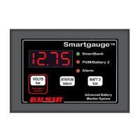
Charge status can be manually set to any value between 0 and 100%. Enter the set-up
menu as usual, then press the SET key until “Cxxx” is displayed. “C” signies charge
status. The xxx displayed will be the current calculated charge status. Pressing the
SELECT button will scroll up to and including 100 then cycle to zero and start again.
When the desired value is displayed, press the VOLTS key. The display will ash to
show the value has been stored. The display will then move onto the next menu item.
Alternatively, pressing the EXIT button will write the value to memory then exit the
set-up menu.
There are two levels of alarm settings in Smartgauge™. The rst is the Primary Alarm which can be set OFF or can
be used to access low/high voltage or low SoC function. See Section 7.0 for information regarding alarm outputs.
Primary Alarm:
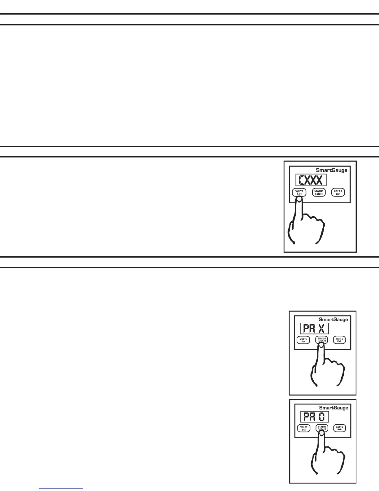
On entering this section of the set-up menu the display will show “PA x”. PA signifying Primary Alarm. “x” displaying
either “O” “ U” “ S”. or “t”. “O” means alarms are switched Off.
“U” means Uoltage (Voltage) alarm is enabled, “S” means low Status alarm is enabled. “t”
means a timed low status alarm is enabled. “S” and “t” type alarms are more fully described
under their respective headings. The SELECT button will scroll round them. The SET button
will set the desired alarm. The display will ash showing the value was written to memory.
Changing the alarm type will cancel any currently active alarms and reset the timed alarm
timers to the user’s programmed default value.
On selecting “PA O” the display will ash and then move onto the next item in the set-up
menu, Secondary Alarm.
Individual Alarm Selection:
Set-up mode – Voltage Alarm:
1. On selecting “PA U” the display will ash to show the value was written to memory. The dis-
play will then show either “Hi” or “Lo”. The SELECT button will alternate between these two
options. “Hi” sets a high-voltage alarm. “Lo” sets a low-voltage alarm. Pressing SET will store
the value.
2. The display will then show “xx.xx” which is the lower voltage trip point. Once this is set (using
the SELECT and SET buttons) the display will again show “xx.xx” which is the upper voltage
trip point.