4
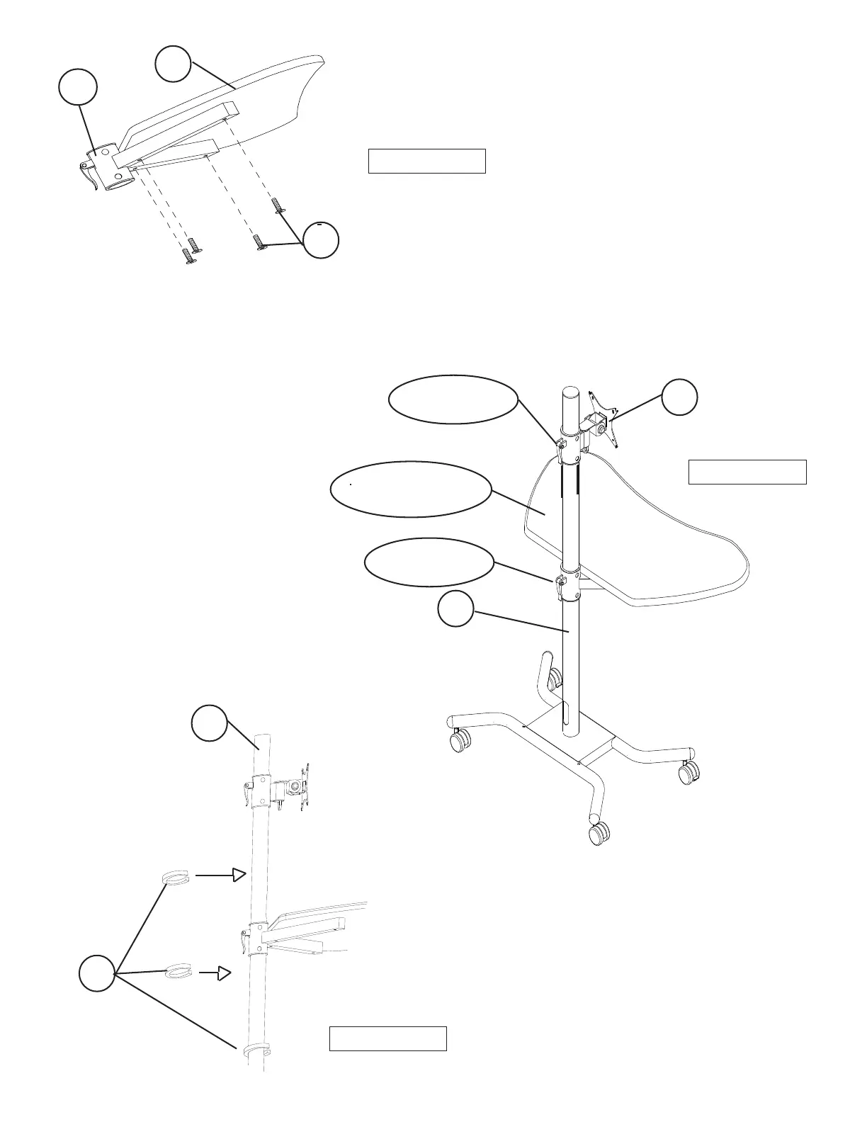
7.) Snap-on three Cable Ties (H) onto the
Pole (P1) to help with wire management
as shown in illustration #5.
90329_08-24-12
Illustration # 3
4.) Attach the Top Panel (P-4) to the Top Frame (P-3) using four
Screws (E) as shown in illustration #3.
E
P4
P3
5.) Open up the Clamp Lever on the Top Panel Assembly. Place it on the Pole (P-1) and slide it
down to the height level you like. Lock the Clamp Lever down to hold the Top Panel assembly
in place on the Pole. See illustration #4.
H
P1
6.) Open the Clamp Lever on
the Monitor Mount (P-5) and
slide it down the Pole (P-1)
to the height you like. Lock
the Clamp Lever down to hold
the Monitor Mount in place.
Note: Pop the plastic caps off the
Monitor Mount(P-5) and use two
Wrench (G) to adjust tilt tension if
needed.
Illustration # 5
Illustration # 4
P1
Clamp Lever
Top Panel
Assembly
P5
Clamp Lever


 To Previous Page
 Loading...