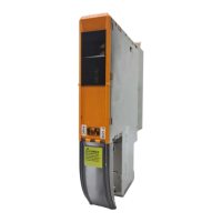
8BVI0014HWD0.000-1
Data sheet V 1.4 1
8BVI0014HWD0.000-1
1 General information
•
Uncontrolled and safe stops integrated
•
Integrated connection for motor holding brake and temperature sensor
•
2 slots for ACOPOSmulti plug-in modules
•
2-axis modules contain two complete standalone inverters in one inverter module
2 Order data
Model number Short description Figure
Wall mounting
8BVI0014HWD0.000-1 ACOPOSmulti inverter module 1.9 A, HV, wall mounting, 2 axes
Required accessories
Terminal block sets
8BZVI0055D0.000-1A Screw clamp set for ACOPOSmulti 8BVI00xxHxD0 modules: 1x
8TB2112.2010-00, 1x 8TB2108.2010-00, 1x 8TB2104.203L-00,
1x 8TB2104.203F-00, 1x 8TB3104.204G-11, 1x
8TB3104.204K-11
8BZVI0055D0.500-1A 50x Screw clamp terminal block set for ACOPOS-
multi modules 8BVI00xxHxD0: 1x 8TB2112.2010-00, 1x
8TB2108.2010-00, 1x 8TB2104.203L-00, 1x 8TB2104.203F-00,
1x 8TB3104.204G-11, 1x 8TB3104.204K-11
8BZVI0055D0.A00-1A 100x Screw clamp terminal block set for ACOPOS-
multi modules 8BVI00xxHxD0: 1x 8TB2112.2010-00, 1x
8TB2108.2010-00, 1x 8TB2104.203L-00, 1x 8TB2104.203F-00,
1x 8TB3104.204G-11, 1x 8TB3104.204K-11
Optional accessories
Accessory sets
8BXB000.0000-00 ACPmulti accessory set for encoder buffering consisting of: 1
lithium battery AA 3.6 V; 1 protective cap for battery holder
Fan modules
8BXF001.0000-00 ACOPOSmulti fan module, replacement fan for ACOPOSmulti
modules (8BxP / 8B0C / 8BVI / 8BVE / 8B0K)
Plug-in modules
8BAC0120.000-1 ACOPOSmulti plug-in module, EnDat 2.1 interface
8BAC0120.001-2 ACOPOSmulti plug-in module, EnDat 2.2 interface
8BAC0121.000-1 ACOPOSmulti plug-in module, HIPERFACE interface
8BAC0122.000-1 ACOPOSmulti plug-in module, resolver interface 10 kHz
8BAC0123.000-1 ACOPOSmulti plug-in module, incremental encoder and SSI ab-
solute encoder interface for RS422 signals
8BAC0123.001-1 ACOPOSmulti plug-in module, incremental encoder interface for
5 V single-ended and 5 V differential signals
8BAC0123.002-1 ACOPOSmulti plug-in module, incremental encoder interface for
24 V single-ended and 24 V differential signals
8BAC0124.000-1 ACOPOSmulti plug-in module, SinCos interface
8BAC0125.000-1 ACOPOSmulti plug-in module, SinCos EnDat 2.1/SSI interface
8BAC0130.000-1 ACOPOSmulti plug-in module, 2 digital outputs, 50 mA, max.
62.5 kHz, 2 digital outputs, 500 mA, max. 1.25 kHz, 2 digital
inputs 24 VDC
8BAC0130.001-1 ACOPOSmulti plug-in module, 2 digital outputs, 50 mA, max.
62.5 kHz, 4 digital outputs, 500 mA, max. 1.25 kHz
8BAC0132.000-1 ACOPOSmulti plug-in module, 4 analog inputs ±10 V
8BAC0133.000-1 ACOPOSmulti plug-in module, 3 RS422 outputs for ABR en-
coder emulation, 1 Mhz
POWERLINK cable
X20CA0E61.00020 POWERLINK connection cable, RJ45 to RJ45, 0.2 m
X20CA0E61.00025 POWERLINK connection cable, RJ45 to RJ45, 025 m
X20CA0E61.00030 POWERLINK connection cable, RJ45 to RJ45, 03 m
X20CA0E61.00035 POWERLINK connection cable, RJ45 to RJ45, 035 m
X20CA0E61.00050 POWERLINK connection cable, RJ45 to RJ45, 0.5 m
X20CA0E61.00100 POWERLINK connection cable, RJ45 to RJ45, 1 m
Shield component sets
8SCS000.0000-00 ACOPOSmulti shield component set: 1 shield plate 1x type 0, 1
hose clamp, B 9 mm, D 12-22 mm
8SCS002.0000-00 ACOPOSmulti shield component set: 1x clamping plate; 2x
clamps D 4-13.5 mm; 4x screws
Table 1: 8BVI0014HWD0.000-1 - Order data

 Loading...