EasyManua.ls Logo

B&R 8I0IF109.400-2 User Manual

B&R 8I0IF109.400-2
36 pages
To Next Page IconTo Next Page
Page #1 background imageLoading...
Page #1 background image
ACOPOSinverter X64
ACOPOSinverter P64new
Migration manual
Version: 1.20 (December 2019)
Order no.: MAACPIX64-ENG
Translation of the original documentation
All values in this manual are current as of its creation. We reserve the right to change the contents of this manual
without notice. B&R Industrial Automation GmbH is not liable for technical or editorial errors and defects in this
manual. In addition, B&R Industrial Automation GmbH assumes no liability for damages that are directly or indirectly
attributable to the delivery, performance or use of this material. We point out that the software and hardware
designations and brand names of the respective companies used in this document are subject to general trademark,
brand or patent protection.
Question and Answer IconNeed help?

Do you have a question about the B&R 8I0IF109.400-2 and is the answer not in the manual?

B&R 8I0IF109.400-2 Specifications

General IconGeneral
BrandB&R
Model8I0IF109.400-2
CategoryInverter
LanguageEnglish

Summary

Safety Information

Personnel Qualifications

Specifies required skills, knowledge, and training for personnel working with the product.

Intended Use

Defines the product's intended applications and operational limitations.

Product-Related Information

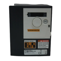
Highlights critical product-specific safety warnings, including electric shock and explosion hazards.

General Information

Comparison of Order Numbers

Lists and compares order numbers for different variants of the ACOPOSinverter X64 and P64new.

Installation

Dimensions and Drill Hole Patterns

Compares the physical dimensions and mounting hole patterns of the ACOPOSinverter P64new and X64.

Input and Output Circuit Diagram

Explains the input and output connections, terminal functions, and electrical characteristics.

ACOPOSinverter X64 I/O Details

Describes the specific input/output terminals and electrical characteristics of the ACOPOSinverter X64.

Interfaces

X2X Link

Details the X2X Link communication interface, its general information, order data, and technical specifications.

LED Status Indicators

Explains the meaning of various LED status indicators on the X2X Link interface module.

Pinout

Shows the pinout diagram for the X2X Link interface module.

Implementation

Distinction and Configuration

Highlights differences in project compatibility and device configuration at runtime.

Control Behavior Analysis

Compares the control behavior, sampling rates, and dynamics between ACOPOSinverter X64 and P64new.

UFT Parameter Analysis

Analyzes control behavior for specific UFT parameter settings (L, P, NLD) across measurement series.

Application-based Differences

Functionality Changes

Covers unavailability of edge counters, high-speed outputs, brake control, and rotation direction settings.

Control and Parameter Migrations

Explains differences in auto-tuning, control words (CMDD, CMI), parameter resets, and motor nameplate switching.

Access, Fallback, and Safety Features

Discusses access restrictions, fallback speed, safety functions, and PI(D) control availability.

Problems and Solutions

Boot Loop Resolution

Provides a procedure to resolve issues where the ACOPOSinverter P64new gets stuck in a boot loop.

Related product manuals