EasyManua.ls Logo

Bang & Olufsen Beogram CD 5500 User Manual

Bang & Olufsen Beogram CD 5500
66 pages
To Next Page IconTo Next Page
Page #1 background imageLoading...
Page #1 background image
Beogram
CD
5500
Type
5131,
5132,
5133,
5434,
5135
Beogram
CD
6500
Type
5136,
5137,
5138,
5139,
5140
Beogram
CD
7000
Type
5151,
5152,
5153,
5154,
5155
CD-Mechanism
Version
II
Beogram
CD
7000
Service
Manual
Danish,
English
BANG
&
OLUFSEN
Question and Answer IconNeed help?

Do you have a question about the Bang & Olufsen Beogram CD 5500 and is the answer not in the manual?
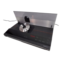
Bang & Olufsen Beogram CD 5500 Specifications

General IconGeneral
BrandBang & Olufsen
ModelBeogram CD 5500
CategoryCD Player
LanguageEnglish

Summary

Technical Specifications

Block Diagram

List of Electrical Parts

Mounting

Instructions and diagrams for mounting electronic components.

Dismounting

Procedures and diagrams for removing electronic components.

Precautions

Important safety and handling advice for electrical parts.

Standard Resistors

PCB 1, 8005217 Display

PCB 2, 8005218 Contact PCB

PCB 5, 8005220 Decoder

Mechanical Partslist

Chassis

Diagram illustrating the main chassis assembly and its components.

Screws, washers, etc.

List of screws, washers, and other small hardware used in assembly.

Mechanical Adjustments

Height of drive mechanism

Procedure to adjust the height of the CD drive mechanism.

Centring of drive mechanism

Procedure to centre the CD drive mechanism assembly.

Centring of bracket for disc clamping magnet

Height of bracket for disc clamping magnet

Stop position for disc drawer

Height of front edge of disc drawer

Electric Adjustments

Brightness

Procedure for adjusting the laser brightness.

+5V power supply

Procedure to check and verify the +5V power supply.

Check, Repair and Adjustment of the CD Mechanism

Servicing the RAFOC unit

Replacing the servo PCB30, RAFOC unit pos. no. 9607 or focusing unit pos, no. 9604

Adjustment of DC focus offset

Checking the angle setting

Adjusting the angle setting

Adjustment of the angle setting is performed as follows

Replacing the flexible PCB pos. 9609

Replacing the focusing unit pos. 9604

Check of laser supply

Adjusting the laser current

Check of disc motor system

Measure with an oscilloscope

Examples of wave forms

Disassembly

Transport protection

Instructions for removing transport screws before operation.

Front panel

Disc tray

Disc holder

CD mechanism

Cord pulley Pos. no. 9014

Tray motor Pos. no. 06M1

Repair Hints

Service program

Steps to enter and utilize the service program for diagnostics.

IC pin survey

Mains Voltages for Transformer 8005169

Insulation Test

Insulation test for Beogram CD5500

Procedure for performing insulation testing on the Beogram CD5500.

Circuit Description

Introduction

Overview of the Beogram CD 5500 and its main IC sets.

Control/monitoring

Description of the control and monitoring circuits in the CD player.

Motor circuit for CD tray

Explanation of the CD tray motor control circuit operation.

Time-out function

Electric operation

The analog filter

Digital output

List of Electrical Parts

Laser current

List of Mechanical Parts

Focus off-set

Procedure for adjusting the focus offset setting.

List of mechanical parts

List of Mechanical Parts

List of Electrical Parts

Related product manuals