Do you have a question about the Bang & Olufsen beomaster 3000 and is the answer not in the manual?
Audio Frequency section, power supply, and control circuits.
Adjust detector using a distortion meter for minimum distortion and 0V output.
Adjust 1R75 using a frequency counter or B&O voltmeter for proper stereo decoding.
Adjust MW circuit voltages and frequencies for 1610kHz, 1500kHz, and 575kHz.
Adjust LW circuit voltages and frequencies for 330kHz and 160kHz.
Adjust IF circuits for maximum symmetrical IF curve using a sweep generator.
Power output, distortion, frequency response, and other audio parameters.
FM range, sensitivity, selectivity, and distortion for various models.
LW/MW range, sensitivity, S/N ratio, and other parameters.
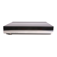
Remove bottom screws and detach the bottom panel from the rear plate.
Remove rear plate screws and top panel screws to detach the top panel.
Unscrew the control panel and remove it, taking care with contact springs.
| Frequency Response | 20 Hz - 20 kHz |
|---|---|
| Input Sensitivity | Phono: 2.6 mV, Tape: 180 mV |
| Weight | 8.6 kg |
| FM range | 87.5 - 108 MHz |
| Total Harmonic Distortion | < 0.15% |
| Intermodulation | 0.1% |