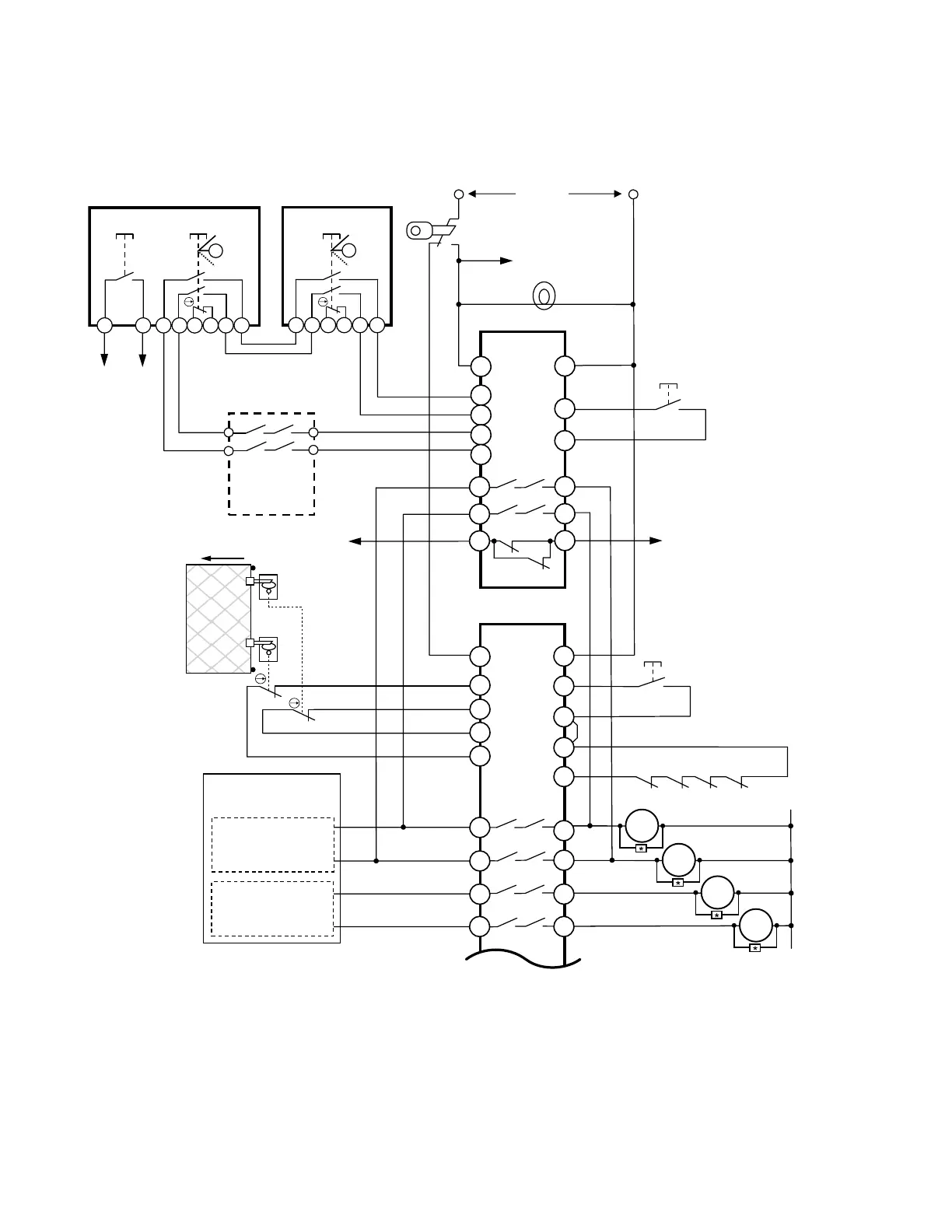
Wiring Example; Gate Monitoring and Speed Monitoring Applications
See notes following figure.
To/From
Inch/Jog or
Hold-to-Run
Machine
Control
(3)
Enabling Device #1
+24Vdc
Bypass Mode
Select Switch
(1)
To Machine Control
“Bypass Mode”
(3)
Bypass Indicator
T
1
2
3
ED1G-L21SM-1N
T
1
2
3
ED1G-L21SMB-1N
ES-UA-5A
K1 K2
MPCE
1
M1 M2 M3 M4
Monitoring Circuit
Reset
Enabling Device #2 .. #n
ES-FA-11 AA
K1 K2
From Reduced
Speed Machine
Control
(3)
To Reduced
Speed Machine
Control
(3)
Safe Speed
Monitoring
Module
(Optional)
(4)
Reset
(2)
(5)
OPEN
7 8 1 3 5 6 4 2 1 3 4 2
A1
S11
S21
S22
S12
13
23
33
14
24
34
A2
S33
S34
* Arc Suppressor (see warning)
MPCE
2
MPCE
3
MPCE
4
A1
S11
S21
S22
S12
13
23
33
S31
S32
24
14
34
4443
A2
S34
S33
Functions requiring
bypass
Functions not
requiring bypass
Machine Control
Circuits
5 6
1. Selection of the enabling device must be capable of being supervised.
2. In this example, the safety module monitoring the enabling device(s) is configured for manual reset, requiring a separate action
before the bypass can occur.
3. Several signals are used to allow the bypass of the safeguard, including:
• The Bypass Mode Selector switch sends a signal to the machine control to enter a reduced performance mode (e.g., inch/jog,
slow speed, etc.),
• The enabling switch (via the N.C. output of the ES-FA-11A safety module) "enables" the slow/reduced speed machine control
function and bypasses the safeguard with the N.O. outputs, and
ED1G Enabling Switch
8 www.bannerengineering.com - tel: 763-544-3164 P/N 151822 Rev. B