PUMP HEAD INSTALLATION
The pump head is connected to driver unit by two m4 screws.
Insert the two screws into the mounting holes, connect the pump head
with the driver unit end to end, then tighten the screws.
To connect two or more pump heads, longer screws are needed.
PROMPT:
Try your best to tighten the two screws in the same degree. Do not
over-tighten the screws to prevent the support block from deforming
and buzz.
If the wall thickness of tubing is not standard, you can adjust the
occlusion as follows: first load the tubing, and push the lever to the left
end to make the occlusion maximum. Place the inlet of the tubing into
water and blow from the outlet, there are blebs. Then push the lever
to the right till there are exactly no blebs.
If there are still blebs after push the lever to the right end, it suggests
that the wall thickness of the tubing is too thin and beyond the appli-
cable range.
LongerPump
TM
YZ Series
PUMP HEAD OPERATING
Press down lever and push back to left to open pump head.
Push tubing clamps at arrowhead direction and load tubing.
Press down lever and push back to right to close pump head.
ATTENTION
The tubing clamp on both sides of the compression block can fit differ-
ent sizes of tubing automatically. Don’t need to adjust.
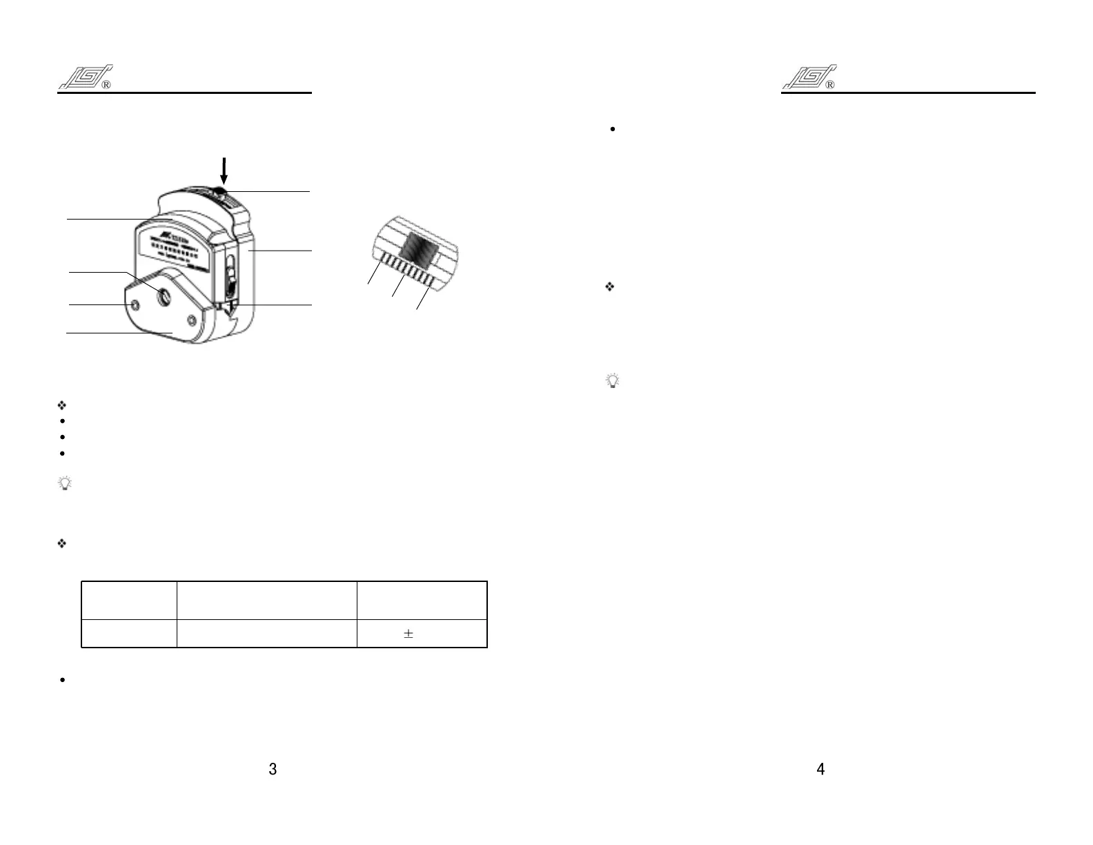
PUMP HEAD OCCLUSION ADJUSTMENT(see K view)
YZ1515w pump head direction for use
K VIEW
A
B
k
Mounting
Holes
Lever
Compression
Block
Rotor
Base
Support
Block
Tubing
Clamp
YZ1515w
PUMP HEAD APPLICABLE TUBING
TUBING WALL
THICKNESS
YZ1515W
13
#
,14
#
,16
#
,25
#
,17
#
,18
#
1.6 0.3(mm)
For standard wall thickness tubing, the lever should be in the middle of
the index scale.
LongerPump
TM
YZ Series