Do you have a question about the BAOJIE BJ-UV55 and is the answer not in the manual?
Install the mounting bracket using supplied self-tapping screws and flat washers.
Secure the transceiver using supplied hexagonal screws after mounting bracket is fixed.
Mount the transceiver body at an inclined angle using the bracket's screw grooves.
Connect the DC power cable to the vehicle battery terminal via the shortest route.
Wrap the power cable to protect it from heat, moisture, and ignition system.
Protect the fuse holder and the entire power cable with heat-resistant adhesive tape.
Disconnect negative battery terminal connections before connecting transceiver to prevent short-circuits.
Ensure correct polarity by connecting red wire to positive and black wire to negative battery terminals.
Use the full power cable length and do not remove the fuse holder.
Reconnect all wiring to the negative battery terminal after connecting the transceiver.
Plug the DC power cable into the transceiver, ensuring the locking tab clicks.
Requires an independent 13.8V DC power supply with at least 12A continuous capacity.
Connect all cables before powering the DC supply and ensure correct polarity.
Connect the DC power supply cable to the transceiver, ensuring the locking tab clicks.
Use only specified fuse types and rated values to prevent transceiver damage.
Install a highly efficient antenna with 50 Ohm impedance and low loss coaxial feeder.
Use 50 Ohm impedance to maintain performance and prevent interference or damage.
Prohibited; transmitting without antenna or matched load will damage the transceiver.
Fixed radio stations must have a lightning arrester to prevent fire or electric shock damage.
| Brand | BAOJIE |
|---|---|
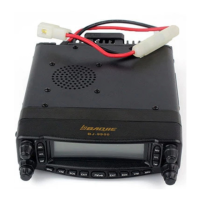
| Model | BJ-UV55 |
| Category | Transceiver |
| Language | English |