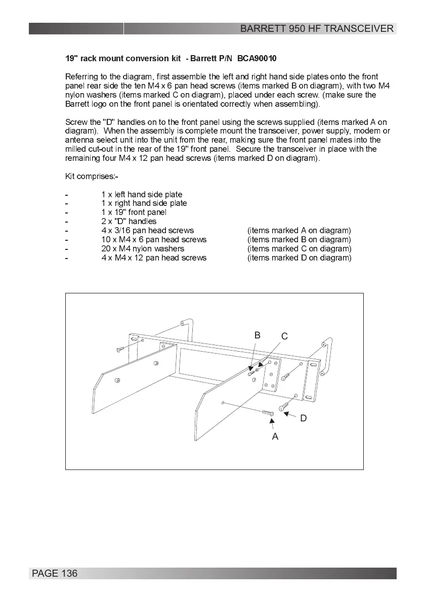
Referring to the diagram, first assemble the left and right hand side plates onto the front
panel rear side the ten M4 x 6 pan head screws (items marked B on diagram), with two M4
nylon washers (items marked C on diagram), placed under each screw. (make sure the
Barrett logo on the front panel is orientated correctly when assembling).
Screw the "D" handles on to the front panel using the screws supplied (items marked A on
diagram). When the assembly is complete mount the transceiver, power supply, modem or
antenna select unit into the unit from the rear, making sure the front panel mates into the
milled cut-out in the rear of the 19" front panel. Secure the transceiver in place with the
remaining four M4 x 12 pan head screws (items marked D on diagram).
Kit comprises:-
- 1 x left hand side plate
- 1 x right hand side plate
- 1 x 19" front panel
- 2 x "D" handles
- 4 x 3/16 pan head screws (items marked A on diagram)
- 10 x M4 x 6 pan head screws (items marked B on diagram)
- 20 x M4 nylon washers (items marked C on diagram)
- 4 x M4 x 12 pan head screws (items marked D on diagram)
19" rack mount conversion kit - Barrett P/N BCA90010
A
C
D
B
BARRETT 950 HF TRANSCEIVER
PAGE 136