Pagina N°.
Page Nr.
Edizione
Edition
S.p.A
11-93
22
Whenever the turret is disassembled, check the state of the following elements which will have to be replaced in
case of a negative result:
- 308 main gasket
- all retaining rings type (O-ring)
- 032 cushion pads
And the following elements (only when the central body has been completely disassembled):
- cam surfaces
- rollers
- HIRTH couplings
- all gears
- support plate of the 003 ring gear with the 002 one.
FROM THE TOP SIDE
Take off the 044 top cover, remove the screws 300, extract the 042 proximity support complete of proximity 301;
take off the 049 support complete of proximity 313, remove the 046a washers, extract the 200 electromagnet, extract
the 017 lock with related 047 spring.
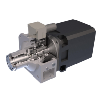
Remove the 019 cover from the two sides, extract the 018 shock absorbing pins complete of 032 pads.
FROM THE REAR SIDE
Take off the 011 cover, remove the screws 302 and remove the 043 encoder support complete of 160 encoder, take
of the 303 seeger, remove the 030 thrust block and the 304 bearing.
FROM THE FRONT SIDE
Take off the toolholder disk, remove the screws 305, take off the dowels 306. Move the push rod 700 towards outside
(
Ú ), extract the entire central body composed by 003 mobile ring gear, 005 indexing head, 006 roller carrier set,
007 spider set, 020 ring nut, 307 belleville washers, 025 - 026 spacers.
If dismounting this set too were necessary, unscrew the ring nut with a particular tool and extract all the other
components.
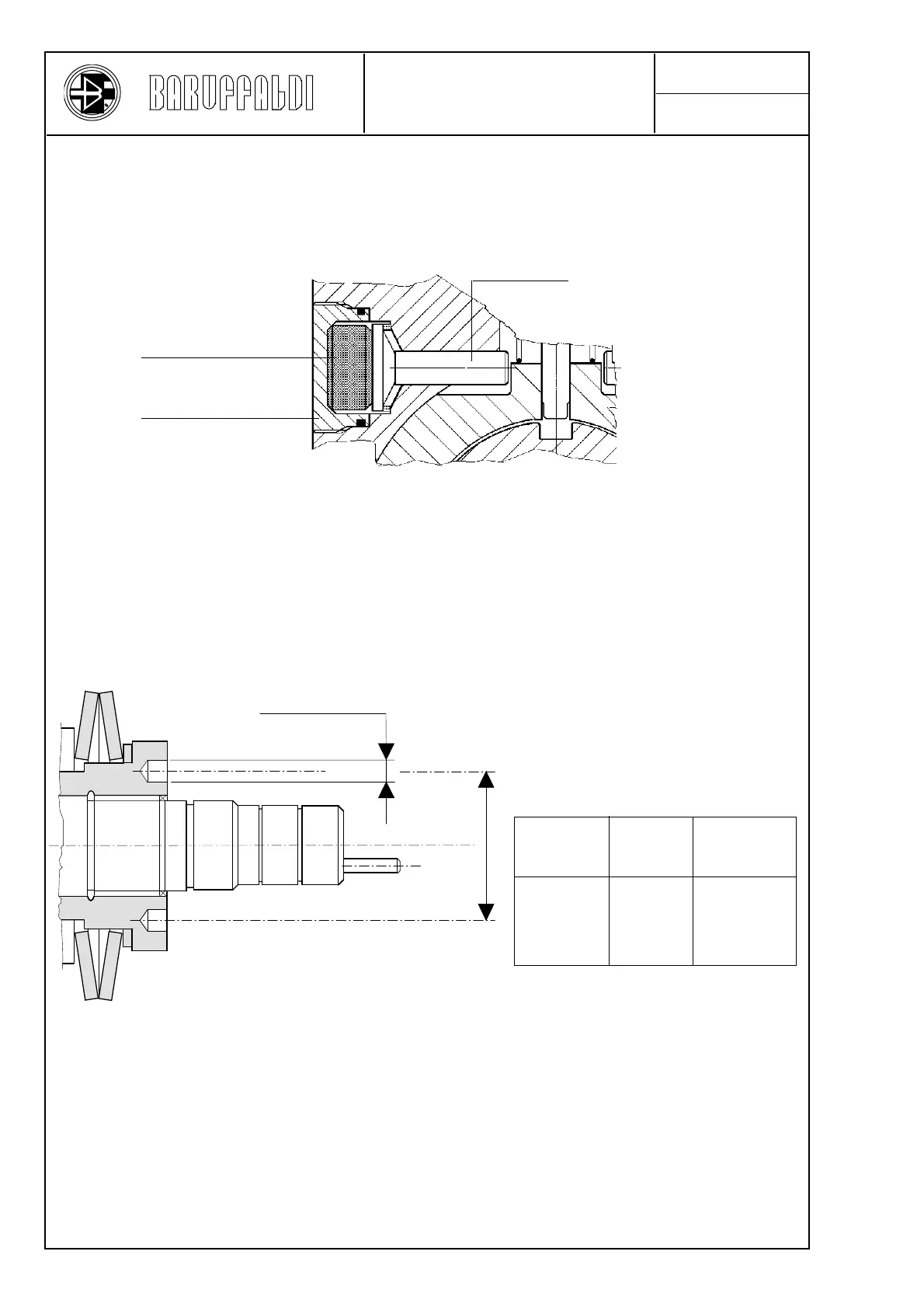
Turret
size
Diameter
R (mm)
44
44
56
56
TOEM 120
TOEM 160
TOEM 200
TOEM 250
8,25
8,25
8,25
8,25
Diameter
S (mm)
R
S n°4
018
032
019
TURRET DISASSEMBLY
(Related to the indexing
components)
 Loading...