If adjustment of the corner frequency is required:
a. Rotate the Underfrequency
control fully counter-
clockwise.
b. Reduce the generator frequency from nominal
(either 50 Hz or 60 Hz) to the desir
ed corner
frequency.
c. Slowly adjust the Unde
rfrequency control clock-
wise until the generator output voltage just starts to
decrease.
Field Flashing
When the controller is operated with the generator for the
first time, the polar
ity of the field’s resid
ual magnetism may
not be correct or the magnitude may not be high enough. If
generator voltage does not increase after startup, stop the
prime mover and perform the following steps.
1. With the prime mover at rest, connect a dc source in
series with a
3 to 5 Ω limiting resistor to the field’s
positive (F+) and negative (F–) terminals. The dc
source should not be grounded and should not have an
output greater than 12 Vdc.
2. Apply the dc vo
ltage for approximately 3 seconds, then
remove it.
3. With controller terminals 3 and 4 disconnected, start the
prime mover
and measure the voltage at the generator
output terminals.
4. If the voltage is greater than
6 Vac, voltage buildup
should be successful and controller terminals 3 and 4
can be reconnected. If less than 6 Vac is measured,
repeat steps 1 through 3. If repeating these steps does
not result in generator voltage buildup, contact Basler
Electric.
OPERATIONAL TEST
1. Connect the analog voltage controller as shown in
Figure 9. Do not apply pow
er. Ensure that the light
bulbs are rated for 120 volts and less than 100 watts.
2. Adjust the controller’s Volt
age control and remote
voltage adjust rheostat (if used) fully counterclockwise.
3. Apply 240 Vac, 60 Hz power to the controller. The light
bulbs should fl
ash momentarily.
4. Slowly adjust the contro
ller’s Voltage control clockwise.
Results
1. Before minimum luminance i
s reached, the light bulbs
should attain maximum luminance to signify the
regulation point.
2. At the regulation po
int, a small change in the Voltage
control or remote voltage adjust rheostat position
should turn the light bulbs on or off.
CONTROLLER DIFFERENCES
Previous versions of the AVC63-4 controller, sold prior to
mid-2003, are slig
htly different in appearance and control
adjustment.
Your controller version can be determined by the location of
the heat sinks. Figure 10 sho
ws the heat sink location on the
previous and current version of the AVC63-4.
Adjustment of the Underfrequency Control is different on
previous versi
ons of the AVC63-4. When adjusting the
Underfrequency Control on previous versions, clockwise
rotation decreases the corner frequency and counter-
clockwise rotation increases the corner frequency.
References to the rotation of the Underfrequency control in
this publication should be reversed when adjusting the
corner frequency on previous versions of the AVC63-4.
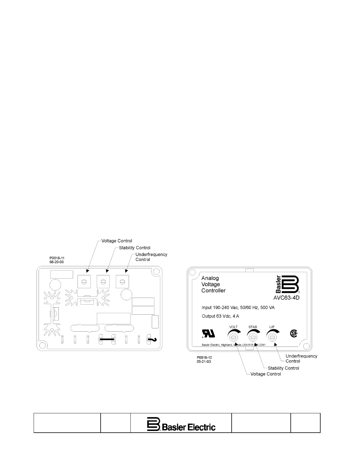
Figure 1. AVC63-4 Potentiometer Control Locations
Figure 2. AVC63-4D Potentiometer Control Locations
Publication
9166800890
Revision
A
First Printing: 09/03
Revised: 04/07
Page
3
 Loading...


