2-4 BE1-51 Controls and Indicators 9137200997 Rev D
TAP Selector
Current Sensing
Terminals
TAP
Range
Plate or
Pickup
A B C D E F G H I J ØA ØB ØC N
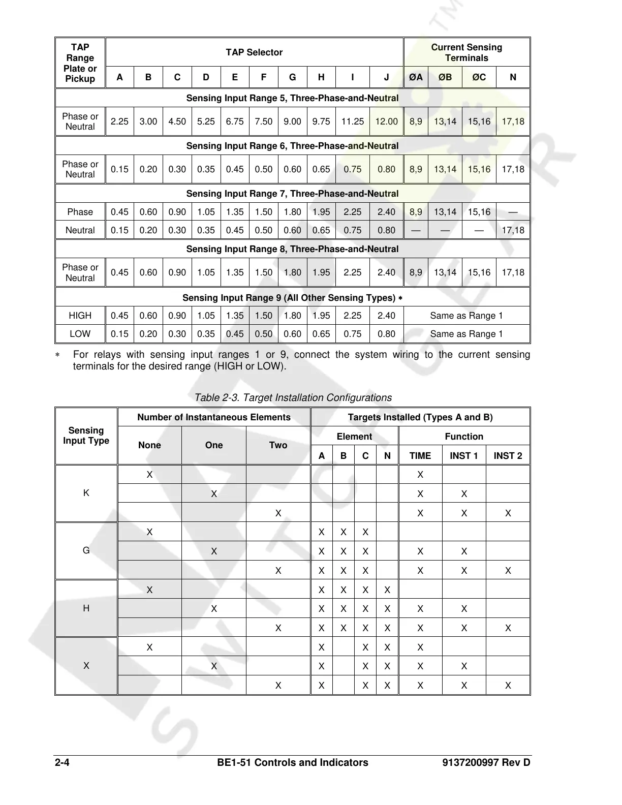
Sensing Input Range 5, Three-Phase-and-Neutral
Phase or
Neutral
2.25 3.00 4.50 5.25 6.75 7.50 9.00 9.75 11.25 12.00 8,9 13,14 15,16 17,18
Sensing Input Range 6, Three-Phase-and-Neutral
Phase or
Neutral
0.15 0.20 0.30 0.35 0.45 0.50 0.60 0.65 0.75 0.80 8,9 13,14 15,16 17,18
Sensing Input Range 7, Three-Phase-and-Neutral
Phase 0.45 0.60 0.90 1.05 1.35 1.50 1.80 1.95 2.25 2.40 8,9 13,14 15,16 —
Neutral 0.15 0.20 0.30 0.35 0.45 0.50 0.60 0.65 0.75 0.80 — — — 17,18
Sensing Input Range 8, Three-Phase-and-Neutral
Phase or
Neutral
0.45 0.60 0.90 1.05 1.35 1.50 1.80 1.95 2.25 2.40 8,9 13,14 15,16 17,18
Sensing Input Range 9 (All Other Sensing Types) ∗
HIGH 0.45 0.60 0.90 1.05 1.35 1.50 1.80 1.95 2.25 2.40 Same as Range 1
LOW 0.15 0.20 0.30 0.35 0.45 0.50 0.60 0.65 0.75 0.80 Same as Range 1
∗ For relays with sensing input ranges 1 or 9, connect the system wiring to the current sensing
terminals for the desired range (HIGH or LOW).
Table 2-3. Target Installation Configurations
Number of Instantaneous Elements Targets Installed (Types A and B)
Element Function
Sensing
Input Type
None One Two
A B C N TIME INST 1 INST 2
X X
X X X
K
X X X X
X X X X
X X X X X X
G
X X X X X X X
X X X X X
X X X X X X X
H
X X X X X X X X
X X X X X
X X X X X X
X
X X X X X X X
Courtesy of NationalSwitchgear.com