EasyManua.ls Logo

Basler ICRM-7 - User Manual

Basler ICRM-7
4 pages
Print Icon
To Next Page IconTo Next Page
Loading...
Publication
9387900990
Revision
A
First Printing: 02/05
Revised: 08/05
Copyright
2005
FOR
INRUSH CURRENT
REDUCTION MODULE
I
C
RM-7
,
I
C
RM-1
5
INTRODUCTION
The Inrush Current Reduction Module (ICRM) prevents damage to a protected voltage regulator during power-up
by limiting inrush current to a safe level. Without inrush protection, the inrush current is limited only by the level of
the power source impedance. The lower the impedance, the greater the risk of damaging the regulator from
excessive inrush current. Devices with a pulse-width modulated (PWM) power stage are especially vulnerable to
high inrush current due to a large amount of capacitance inherent to the design. However, voltage regulators that
use SCR-type power stages do not require the protection of an ICRM since these regulators do not have a large
amount of capacitance in the power stage.
When a voltage regulator with a PWM power stage is energized, the ICRM limits the inrush current by adding a
high level of resistance in series with the voltage regulator power input. Once the inrush current subsides, the
series resistance diminishes quickly to allow nominal, steady-state current flow.
APPLICATION
Applications where a voltage regulator is powered by a permanent magnet generator (PMG), auxiliary winding, or
generator output (shunt fed) usually do not require the protection of an ICRM. These sources usually have a
higher source impedance which inherently minimizes inrush current. Also, these sources are typically connected
directly to the voltage regulator with no interposing relays, contactors, or switches. If this is the case, then no
inrush occurs since the source voltage ramps up to its rated value.
However, if rated or near rated voltage is applied to the voltage regulator, then some amount of inrush current is
expected and an ICRM should be considered. Typically, voltage regulators in these applications receive power
from a station service bus that is switched by a relay or contactor. Applications where a PWM type voltage
regulator is powered by a low-impedance source need an ICRM to minimize the amount of inrush current.
To summarize, if the voltage that powers the voltage regulator ramps up to nominal as the generator comes up to
rated speed, then an ICRM is not needed. If this is not the case, an ICRM should be used. If you are unsure
whether your application requires an ICRM, contact Basler Electric Technical Sales Support for assistance.
ICRM Versions
Two versions of the ICRM are available. Each version is uniquely suited to protect a specific family of Basler
Electric products. Table 1 lists each ICRM model, its part number, and the compatible products.
Table 1. ICRM Cross-Reference
Model Number Part Number Compatible Products
ICRM-7 9387900103 DECS-100
ICRM-15 9387900104 AVC63-12, AVC125-10, DECS-200
SPECIFICATIONS
The following electrical and physical specifications, type tests, and certifications apply to the ICRM.
CAUTION
If operating power is removed from an energized ICRM, a minimum interval of
five minutes should elapse before operating power is restored. This cool-down
interval allows the ICRM to regain its ability to limit inrush current.
Question and Answer IconNeed help?

Do you have a question about the Basler ICRM-7 and is the answer not in the manual?

Overview

The Basler Electric Inrush Current Reduction Module (ICRM) is a protective device designed to prevent damage to voltage regulators during power-up by limiting the initial surge of current to a safe level. This is particularly crucial for voltage regulators employing Pulse-Width Modulated (PWM) power stages, which inherently possess a significant amount of capacitance and are therefore more susceptible to high inrush currents. Conversely, voltage regulators utilizing SCR-type power stages generally do not require ICRM protection due to their lower capacitance.

When a PWM-based voltage regulator is energized, the ICRM functions by introducing a high series resistance into the power input of the regulator. This resistance effectively limits the inrush current. Once the initial current surge subsides, the ICRM rapidly reduces its series resistance, allowing for nominal, steady-state current flow to the regulator.

The application of an ICRM is not universally required. For instance, if a voltage regulator is powered by sources such as a Permanent Magnet Generator (PMG), an auxiliary winding, or a generator output (shunt fed), an ICRM is typically unnecessary. These power sources usually exhibit a higher source impedance, which naturally minimizes inrush current. Furthermore, if these sources are connected directly to the voltage regulator without intervening relays, contactors, or switches, inrush current is often negligible as the source voltage gradually ramps up to its rated value.

However, an ICRM should be considered when rated or near-rated voltage is applied abruptly to the voltage regulator, as this scenario is likely to induce significant inrush current. This often occurs in applications where voltage regulators receive power from a station service bus, switched by a relay or contactor. Therefore, a PWM-type voltage regulator powered by a low-impedance source necessitates an ICRM to mitigate inrush current. In summary, if the voltage powering the regulator ramps up to nominal as the generator reaches rated speed, an ICRM is not needed. Otherwise, an ICRM should be employed. Basler Electric Technical Sales Support is available for assistance in determining the necessity of an ICRM for specific applications.

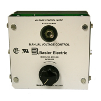
Two versions of the ICRM are available, each tailored to protect specific Basler Electric products. The ICRM-7 (Part Number 9387900103) is compatible with the DECS-100. The ICRM-15 (Part Number 9387900104) is compatible with the AVC63-12, AVC125-10, and DECS-200.

Important Technical Specifications:

  • Input Voltage: 90 to 277 Vac, 90 to 300 Vdc
  • Input Frequency: dc, 50 to 420 Hz
  • Input Current:
    • ICRM-7: 9 Aac
    • ICRM-15: 18 Aac
  • Power Dissipation: 25 W
  • Operating Temperature: -25 to 70°C (-13 to 158°F)
  • Storage Temperature: -40 to 70°C (-40 to 158°F)
  • Weight: 227 g (8 oz)
  • Dielectric Strength: Withstands 2,000 Vac for one minute in accordance with IEC 60255-5.
  • Shock Resistance: Withstands 15 G in three perpendicular planes in accordance with IEC 60255-21-1.
  • Vibration Resistance: Tested in accordance with IEC 60255-21-2. Withstands 2 G in each of three mutually perpendicular axes, swept over the range of 10 to 500 Hz for a total of six sweeps, 15 minutes each sweep.
  • Humidity: Qualified to IEC 68-1, IEC 68-2-28.
  • Certifications:
    • UL Recognition: cURus recognition per UL Standard 508 and CSA Standard C22.2 No. 14.
    • CE Qualification: This product meets or exceeds the standards required for distribution in the European community.

Usage Features:

The ICRM can be installed in any environment where the operating conditions remain within the specified limits. For optimal cooling, the ICRM should be mounted on a vertical surface, with the ventilation holes positioned at the top and bottom of the unit. During operation, the case of the ICRM may become hot, which is normal.

The ICRM is not phase sensitive, meaning it can be used in both single-phase and three-phase operating power applications. Typical connection diagrams are provided in the manual for both types of applications. The terminal connections for compatible voltage regulators are as follows:

  • AVC63-12, AVC125-10: A-OUT to terminal 26, B-OUT to terminal 28, C-OUT to terminal 30.
  • DECS-100: A-OUT to terminal 3, B-OUT to terminal 4, C-OUT to terminal 5.
  • DECS-200: A-OUT to terminal C2, B-OUT to terminal C3, C-OUT to terminal C4.

Wiring requirements, including wire sizing, fuse recommendations, and terminal designations, are subject to the specifications of the voltage regulator. Users should refer to the appropriate device instruction manual for detailed wiring information.

Maintenance Features:

The ICRM contains no serviceable components. In the event of a failure, replacement of the ICRM is recommended.

A critical caution for ICRM operation is related to power restoration. If operating power is removed from an energized ICRM, a minimum cool-down interval of five minutes must elapse before power is restored. This allows the ICRM to regain its ability to effectively limit inrush current.

If the protected device is not receiving operating power, troubleshooting steps include:

  1. Verifying that the ICRM connections between the power source and voltage regulator are correct.
  2. Confirming that the voltage supplied by the power source is sufficient to energize the voltage regulator.

If operating power is applied to the input terminals of the ICRM but no voltage is present at the output terminals, the following procedure should be followed after removing operating power and disconnecting all ICRM wiring:

  1. Connect a suitable ohmmeter across the A-IN and A-OUT terminals. The resistance measured should be approximately 2.0 ohms for the ICRM-7 and 0.5 ohms for the ICRM-15. If an open circuit or short circuit is detected, the ICRM should be replaced.
  2. Repeat this resistance check for the B-IN and B-OUT pair of terminals and the C-IN and C-OUT pair of terminals.

Basler ICRM-7 Specifications

General IconGeneral
BrandBasler
ModelICRM-7
CategoryControl Unit
LanguageEnglish

Related product manuals