Do you have a question about the Battipav SUPREME Series and is the answer not in the manual?
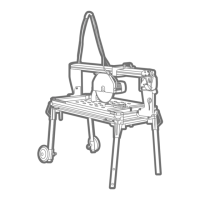
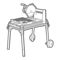
The BATTIPAV SUPREME masonry saw is a robust and versatile machine designed for precision cutting of various construction materials. It is specifically engineered for cutting bricks, natural stone, granite, concrete items, and similar materials up to a thickness of 180 mm. The machine utilizes a wet diamond-tipped tool cutting system, ensuring efficient and clean cuts while minimizing dust. It is intended for use by specialized personnel in the construction sector. The operator works from the narrow side of the machine, with all operating controls within easy reach, positioning the material to be cut on the moving worktop. After starting the machine, the cutting head is moved to bring the tool into contact with the material.
The SUPREME masonry saw comes in various models, each with specific electrical and performance characteristics. For instance, models like 8085, 8100, 8120, 8150, and 8200 operate on 230V 50Hz~, featuring a 2.2kW / 3 hP S6 40% motor. These models typically use a 300/25.4 mm blade, achieve a rotation speed of 2800 min⁻¹, and require a 13A current. The maximum cutting length varies by model, ranging from 850 mm to 2000 mm, with corresponding cutting dimensions. For example, the 8085 model can cut up to 600 x 600 mm, while the 8200 model handles up to 1410 x 1410 mm.
Higher-power models, such as 8260 and 83201, operate on 400V 50Hz~ with a 3.4kW / 4.5 hP S1 motor. These also use a 300/25.4 mm blade and achieve 2800 min⁻¹ rotation speed but require a 16A current. Their cutting lengths extend to 2600 mm and 3200 mm, respectively, accommodating larger materials like 1839 x 1839 mm for the 8260 and 2256 x 2256 mm for the 83201.
The machine's noise level, measured according to UNI EN12418 and EN3744 standards, is 79.8/0.0 dB(A) /mW(A) (LW) and 68.5 dB(A) (LOP), with a maximum LOP of 80.7 dB(C) when operating without load at maximum speed with a 350mm cutting tool (Art. 967). In working conditions, the noise emission can exceed 85 dB(A). The vibration level transmitted to the hand-arm system, measured according to UNI EN ISO 5349-1 when cutting poroton-type bricks (L 280 x L 140 x H 100 mm) with a 350 mm cutting tool (Art. 967), is 1.15 m/s² (0.28m/s²).
The SUPREME masonry saw is designed for wet diamond blade cutting. Recommended materials include ceramic, marble, stone, single-fired ceramic for continuous crown blades, and cement, natural stones, granite, abrasive materials for laser/sectors and turbo blades. Always follow the cutting tool manufacturer's intended use indications.
The machine is equipped with transport handles and, optionally, transport wheels for easy movement. Before transport, ensure the motor carriage is locked, legs are in transport position, the motor head is locked, and the tube-holder rod is out of its housing. For lifting, use a four-arm tie rod with a capacity of at least 200 kg or 20% more than the machine's weight.
To set up the machine for work, loosen the left leg locking pin, lift the leg into the wheel support, and lock it. Tighten the wheel support setscrew. Repeat for the right wheel. For correct positioning, ensure the leg upper hole matches the leg coupling hole before locking. Always hold the machine with the aid of a second person during wheel kit installation and leg locking phases to maintain stability.
The machine must be connected to the power supply via a Residual Current Circuit Breaker (RCCB) with characteristics of 16 A Id 30 mA. Periodically check the RCCB's efficiency by pressing its push-button. Ensure the power supply cable cores' section is adequate for the starting current and length (e.g., 4 mm² for cables up to 50 m). The machine must be connected to an effective earth wire. In case of reverse motor rotation (for specific models), invert the two phase pins inside the power plug using a screwdriver.
Before any blade operation, disconnect the machine from the supply mains. Loosen the five nuts on the blade cover guard and remove it. The blade fixing nut has a left-hand thread and is removed using a 30 mm spanner and a 5 mm Allen wrench. Install the new blade, checking for the correct rotation direction indicated on the tool, then tighten and replace the blade cover.
The control board includes:
Before starting, ensure at least 150 cm of free space around the machine and that the material is properly leaned against the tile stopper.
The laser marker, a Class I laser instrument, accelerates cutting operations by indicating the cutting line on the working table. It activates when the machine is connected to the power supply. Direct exposure to sunlight may reduce its effectiveness, so indoor use is advisable.
The "CUTTING PROGRESS SYSTEM" (Pos. 26) allows precise adjustment of the cutting head's forward or backward movement via a hand wheel on the machine's front upright. Exercise caution due to the accessory's high sensitivity to avoid accidentally locking the cutting tool.
The motor carriage has two registers for vertical play adjustment. To adjust, use a 3 mm Allen wrench to screw both front adjustment dowels (A) until play is eliminated. Repeat for both back adjustment dowels (B). Tighten all four registers equally for smooth movement.
Cleaning is easy by loosening the locking nuts and dismantling the working table. Remove residuals from the recovery tank via the tap at the bottom. After cleaning, replace the working table, observing the distance from the leg support. Regularly clean the sprayer as indicated.
At the end of its lifespan, the machine and its components (polyamide, steel, aluminum, copper, epoxy resin for main casing, submerged pump, and electric motor) must be disposed of according to current legislation. As per European Directive 2012/19/EU, electrical equipment must be collected separately for recovery and recycling, marked with the crossed basket symbol. Packaging should also be disposed of according to regulations. Refer to public administration services for detailed disposal information.
Repairs must only be carried out by qualified personnel using original spare parts to avoid danger. Malfunctions not due to a conformity defect at purchase are excluded from warranty, including: