17
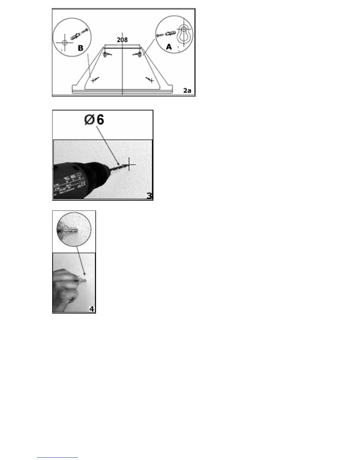
2a) The support screw holes
are indicated by figure A in
this drawing and the
anchoring screw holes are
indicated by figure B.
3) Using a drill bit with a 6 mm
diameter, make holes in the wall on the
positions that you have marked in step
2.
4) Insert rawl plugs into all of the holes that you have
drilled.
Get user manuals: See SafeManuals.com
 Loading...