EasyManua.ls Logo

Baumer URDK 10N8914/S35A - User Manual

Baumer URDK 10N8914/S35A
2 pages
Print Icon
To Next Page IconTo Next Page
Loading...
URDK 10N8914/S35A
10161447
Í?*0.OÂÂ*Â\Î
1/2
Ultraschall-Sensoren
Ultrasonic sensors
Détecteurs à ultrasons
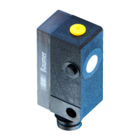
Reflexionsschranke
Retroreflective sensor
Barrière réflex
Canada
Baumer Inc.
CA-Burlington, ON L7M 4B9
Phone +1 (1)905 335-8444
China
Baumer (China) Co., Ltd.
CN-201612 Shanghai
Phone +86 (0)21 6768 7095
Denmark
Baumer A/S
DK-8210 Aarhus V
Phone: +45 (0)8931 7611
France
Baumer SAS
FR-74250 Fillinges
Phone +33 (0)450 392 466
Germany
Baumer GmbH
DE-61169 Friedberg
Phone +49 (0)6031 60 07 0
India
Baumer India Private Limited
IN-411058 Pune
Phone +91 20 66292400
Italy
Baumer Italia S.r.l.
IT-20090 Assago, MI
Phone +39 (0)2 45 70 60 65
Singapore
Baumer (Singapore) Pte. Ltd.
SG-339412 Singapore
Phone +65 6396 4131
Sweden
Baumer A/S
SE-56133 Huskvarna
Phone +46 (0)36 13 94 30
Switzerland
Baumer Electric AG
CH-8501 Frauenfeld
Phone +41 (0)52 728 1313
United Kingdom
Baumer Ltd.
GB-Watchfield, Swindon, SN6 8TZ
Phone +44 (0)1793 783 839
USA
Baumer Ltd.
US-Southington, CT 06489
Phone +1 (1)860 621-2121
www.baumer.com/worldwide
Baumer Electric AG · CH-8501 Frauenfeld
Phone +41 (0)52 728 1122 · Fax +41 (0)52 728 1144
Abmessungen
Dimensions
Dimensions
2,9
7
2,9 15
Teach-in
LED
3
3,2
12
10,4
M8 x 1
6,7 27
17,9
14
Alle Masse in mm
All dimensions in mm
Toutes les dimensions en mm
Elektrischer Anschluss
Connection diagrams
Schéma de raccordement
NPN Schliesser (NO)
NPN make function (NO)
NPN à fermeture (NO)
NPN Öffner (NC)
NPN break function (NC)
NPN à ouverture (NC)
oder
or
ou
0 V
WH (2)
BU (3)
BN (1)
BK (4)
+VS
output
control
NPN
Z
BN = Braun/brown/brun
BK = Schwarz/black/noir
BU = Blau/blue/bleu
WH = Weiss/white/blanc
• Vor dem Anschliessen des Sensors die Anlage spannungsfrei schalten
• Disconnect power before connecting the sensor
• Mettre l’installation hors tension avant le raccordement du détecteur
Anschlussbelegung
Pin assignment
Raccordement
1 / +VS
3 / 0 V
4 / Output
2 / cont/Teach-In
Bedienungsanleitung
Operating instructions
Notice d'utilisation
Teach-in Verriegelung
Teach-in locking
Verrouillage du Teach-in
respectively after the end of the last Teach-in process.
5 min. nach jedem Power-up,
5 min. after every power-up, 5min.après chaque mise sous
bzw. nach dem Ende des letzten Teach-in Vorgangs.
tension resp. après fin du dernier processus Teach-in.
Einstellung der Ausgangsfunktion (NO/NC)
Teach-in-Taste ca. 4s drücken oder externen Teach-
in-Anschluss mit +Vs verbinden bis die LED rot
1. Den Sensor in den Einstellmodus bringen:
blinkt. Taste loslassen bzw. die Verbindung öffnen.
2. Die LED zeigt nun die Ausgangsfunktion an. Grün be-
deutet Schliesser, rot Öffner. Durch kurzes drücken
der Taste oder kurzes verbinden des externen Teach-
in-Anschluss mit +Vs kann die Ausgangsfunktion um-
3. Die gewählte Ausgangsfunktion wird abgespeichert
indem die Teach-in-Taste ca. 2s gedrückt oder der
Programming of output function (NO/NC)
Press the Teach-in button or connect the external
Teach-in wire to +Vs for approx. 4secs until the LED
1. Adjustment mode:
flashes red. Release button or disconnect
2. The LED shows the output funktion of the sensor.
Green indicates NO, red indicates NC. Output
function is changed by either holding down the
3. The chosen output function is saved by holding
down the Teach-in button or by connecting the
Presser le bouton Teach-in ou connecter le fil du
Teach-in externe sur +Vs pendant 4s environ jusqu'à
1. Ajustage:
ce que la LED rouge clignote. Relâcher ensuite le
2. La LED indique la fonction de sortie du détecteur.
Vert pour NO, rouge pour NC. Vous pouvez ainsi
changer la fonction de sortie en appuyant rapidement
sur le bouton Teach-in ou connectant rapidement le
3. Valider la fonction de sortie choisie en pressant le
bouton Teach-in ou en connectant le fil du Teach-in
externe sur +Vs pendant 2s environ. Les LED rouge
Teach-in wire.
Teach-in button or by connecting the external
bouton ou déconnecter le fil.
geschaltet werden.
externe Teach-in-Anschluss ca. 2s mit +Vs verbunden
wird. Bestätigung des erfolgreichen Teach-Vorgangs
durch Leuchten beider LEDs für 2s.
Teach-in wire to +Vs for a short time.
external Teach-in wire to +vs for approx. 2secs.
Successful completion of the Teach-in procedure is
confirmed by both LEDs being "on" for approx. 2secs.
fil du Teach-in externe sur +Vs.
et verte s'allument pendant 2s pour confirmer que
le réglage a bien été pris en compte.
Einstellung der Reflektorposition
Teach-in-Taste ca. 2s drücken oder externen Teach-
in-Anschluss mit +Vs verbinden bis die LED grün
1. Den Sensor in den Einstellmodus bringen:
blinkt. Taste loslassen bzw. die Verbindung öffnen.
2. Die LED blinkt grün. Den Reflektor an die ge-
wünschte Position bringen und die Teach-in-Taste
kurz drücken oder den externen Teach-in-Anschluss
kurz mit +Vs verbinden.
3. Bestätigung des erfolgreichen Teach-Vorgangs durch
Leuchten beider LEDs für 2s.
Teach-in of reflector's position
Press the Teach-in button or connect the white
Teach-in wire to +Vs for approx. 2secs until the LED
1. Adjustment mode:
flashes green. Release button or disconnect
2. LED flashes green. Place the reflector at the
required position and press the Teach-in button
or connect the external white Teach-in wire
3. Successful completion of Teach-in procedure is
confirmed by both LEDs being "on" for approx. 2secs.
Ajustage de la position du réflecteur
Presser le bouton Teach-in ou connecter le Teach-in
externe avec +Vs pendant environ 2 secondes
1. Ajustage:
jusqu'à ce que la LED vert clignote.
2. LED clignote en vert. Placer le réflecteur a la
distance désirée et presser le bouton Teach-in ou
connecter briévement le Teach-in externe (WH)
avec +Vs.
3. La validation de la procédure Teach-in est confirmée
par I'état de fonctionnement des deux LEDs
Teach-in wire.
shortly to +Vs.
Relâcher le bouton ou déconnecter le Teach-in externe.
Réglage de la fonction de sortie (NO/NC)
pendant 2 secs.
Question and Answer IconNeed help?

Do you have a question about the Baumer URDK 10N8914/S35A and is the answer not in the manual?

Overview

This document describes the URDK 10N8914/S35A, a retroreflective ultrasonic sensor designed for industrial applications. It functions as a retroreflective barrier, detecting objects by sensing the interruption of an ultrasonic beam reflected off a dedicated reflector.

Function Description

The URDK 10N8914/S35A operates on the principle of ultrasonic reflection. It emits ultrasonic waves which are then reflected by a designated reflector. When an object passes between the sensor and the reflector, it interrupts this beam, causing a change in the received signal that triggers the output. This makes it suitable for presence detection, counting, and positioning tasks where a reflector can be strategically placed.

The sensor features a Teach-in function, allowing for easy and precise adjustment of its operating parameters. This includes setting the reflector's position (Sde) and configuring the output function (NO/NC - Normally Open/Normally Closed). The Teach-in process can be initiated either via a dedicated button on the sensor or through an external Teach-in wire connected to +Vs. An LED indicator provides visual feedback during the Teach-in process, indicating the current status (e.g., green for reflector position adjustment, red for output function adjustment, and flashing for various states).

The output function can be configured as either Normally Open (NO) or Normally Closed (NC). In NO mode, the output is active when an object is detected (beam interrupted). In NC mode, the output is active when no object is detected (beam uninterrupted). This flexibility allows the sensor to be integrated into various control systems.

Important Technical Specifications

  • Operating Voltage (Vs): 12-30VDC (UL-Class 2).
  • Current Consumption (max., no load): <35mA.
  • Max. Load Current: 200mA.
  • Short Circuit Protection: Yes.
  • Reverse Polarity Protection: Yes.
  • Output State Indication: Green/Red LED. The LED indicates the current output state (green for NO, red for NC) and also provides feedback during Teach-in procedures.
  • Temperature Range: -10...60°C.
  • Protection Class: IP67, indicating protection against dust ingress and temporary immersion in water.
  • Scanning Range (Sd): 0mm...Sde. The actual scanning range depends on the Teach-in configuration.
  • Reflector Position (Sde pot): 40...200mm. This specifies the adjustable range for the reflector's position.
  • Reproducibility: The sensor offers consistent performance, ensuring reliable detection.
  • Temperature Drift: The sensor's performance is stable across its operating temperature range.
  • Max. Tightening Torque: 1Nm for mounting.
  • Dimensions: The sensor has a compact design with an M8 x 1 threaded housing. Key dimensions include a length of 6.7mm, a diameter of 12mm, and a total length of 27mm including the connector. The LED is positioned at 17.9mm from the front face.
  • Electrical Connection: NPN output type.
    • BN (1): +Vs (Brown)
    • BK (4): - output (Black)
    • BU (3): 0V (Blue)
    • WH (2): control (White) - used for external Teach-in.
    • The output can be configured as NPN make function (NO) or NPN break function (NC).

Usage Features

  • Teach-in Functionality: The sensor's primary usage feature is its intuitive Teach-in capability. This allows for quick and accurate setup without manual potentiometer adjustments.
    • Reflector Position Adjustment: To set the reflector position, press the Teach-in button (or connect the external Teach-in wire to +Vs) for approximately 2 seconds until the LED flashes green. Position the reflector at the desired distance and then briefly press the Teach-in button (or connect the external Teach-in wire to +Vs). A successful Teach-in is confirmed by both LEDs being "on" for 2 seconds.
    • Output Function (NO/NC) Programming: To program the output function, press the Teach-in button (or connect the external Teach-in wire to +Vs) for approximately 4 seconds until the LED flashes red. The LED will then indicate the current function (green for NO, red for NC). Briefly pressing the Teach-in button (or connecting the external Teach-in wire to +Vs) toggles between NO and NC. To save the chosen function, press the Teach-in button (or connect the external Teach-in wire to +Vs) for approximately 2 seconds. Successful saving is confirmed by both LEDs being "on" for 2 seconds.
  • Teach-in Locking: For security and to prevent accidental changes, the Teach-in function is locked for 5 minutes after every power-up or after the completion of the last Teach-in process.
  • Visual Indicators: The integrated LED provides clear visual feedback on the sensor's status:
    • LED on: Reflector within correct working distance, no object recognized; output is inactive.
    • LED flashing: Distance to reflector improperly adjusted, adjustment aid; output remains inactive.
    • LED off: Object recognized or reflector out of range; output is active.
  • External Teach-in: The sensor supports external Teach-in via the white wire (WH). If this feature is not used, the Teach-in wire must be connected to GND.
  • Factory Reset: The sensor can be reset to its original factory settings by holding down the Teach-in button (or connecting the external Teach-in wire to +Vs) for more than 6 seconds. Rapid flashing of the LED indicates a successful reset.
  • Pre-connection Safety: Always disconnect power before connecting the sensor to prevent electrical hazards.

Maintenance Features

  • Robust Design: The IP67 protection class ensures the sensor is resistant to dust and water, reducing the need for frequent cleaning or protection in harsh environments.
  • Self-monitoring: The LED indicators provide immediate feedback on the sensor's operational status, allowing for quick diagnosis of issues such as improper reflector positioning.
  • Easy Reset: The factory reset function simplifies troubleshooting by allowing users to quickly revert to default settings if configuration issues arise.
  • Minimal Moving Parts: As an ultrasonic sensor, it lacks moving parts, contributing to its longevity and reducing wear and tear, thus minimizing maintenance requirements.
  • Clear Documentation: The provided manual includes detailed instructions for setup and troubleshooting, facilitating maintenance and ensuring correct operation.

Baumer URDK 10N8914/S35A Specifications

General IconGeneral
BrandBaumer
ModelURDK 10N8914/S35A
CategorySecurity Sensors
LanguageEnglish