bc audio 9/2014 Amplifier No. 9 Owner’s Manual
CONNECTIONS AND CONTROLS
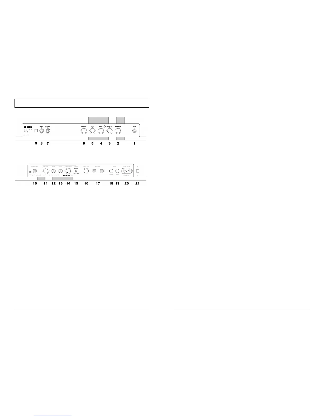
Front Panel
Rear Panel
FRONT PANEL
1. Input Jack
The INPUT jack feeds the Normal and Bright channels simultaneously. Plug a
guitar cable into the INPUT jack, and the other end into your guitar, pedal board
or accordion.
2 & 3. Volume Controls
NORMAL VOL (2) sets the volume level of the Normal Channel, while BRIGHT
VOL (3) sets the volume level of the Bright Channel. No kidding! By mixing Bright
and Normal Channels, you can dial in an infinite variety of mellow to cutting
tones. Both channels are active at all times.
4. Boost Control and Indicator
BOOST sets the amount of additional gain when engaged by the included foot
switch. When engaged, the LED indicator on the front panel and the foot switch
will light. If no foot switch is plugged into the FOOT SWITCH jack (10), the
BOOST is engaged.
5 & 6. Presence and Depth Controls
PRESENCE (6) adjusts the amp’s overall brilliance. DEPTH (5) affects the low
frequency response. These two controls works in the amp’s power section to
change the sound and feel of the amp. Lower PRESENCE settings produce a
4
darker, “browner” sound (yeah, I know), while higher settings produce a brighter,
sharper tone. Higher settings of DEPTH give the amp low-end punch and thump.
You may hear some scratchiness when rotating these controls. This is normal.
7 & 8. Power & Standby Switches
To turn on the amp, move POWER (8) to ON while leaving STANDBY (7) in the
OFF position to allow the tubes to warm up. After a half-minute or so, flip the
STANDBY switch up to the ON position. To turn the amp off, simply flip both
switches down to OFF. There’s no need to put the amp in standby mode when
shutting down.
9. Power Indicator
The Power Indicator lamp will illuminate when power is connected and the
POWER switch (8) is set to ON. If it doesn’t light, the power is not connected, or
the mains fuse (19) has blown.
REAR PANEL
10. Foot Switch Jack
Plug the included foot switch into the FOOT SWITCH jack. The foot switch
controls the Boost function (4).
11-15. Effects Loop (Model A9L Only)
To connect your pedals or outboard effects to the effects loop, run a standard
shielded instrument cable from the SEND jack (12) to the input of the first
outboard device. Run another instrument cable from the output of the last device
to the RETURN jack (13). Adjust SEND LEVEL (11) and RETURN LEVEL (14)
as needed. For best performance with guitar pedals, set SEND LEVEL to 5-7 and
set RETURN LEVEL to 10.
Use the FX LOOP ENGAGE/TRUE BYPASS switch (15) to engage or bypass
the loop. Signal is always present at the SEND jack, regardless of the position of
this switch.
The loop is fully tube-buffered and non-inverting.
16 & 17. Speaker Output Jacks and Impedance Selector
Plug a speaker cable into either SPEAKER jack (17) and the other end into your
speaker cabinet. Be sure to use a speaker cable, not a guitar cable, or damage
to the cable, the amp and your reputation may occur. Set the IMPEDANCE
selector (16) to match the rated impedance of your speaker cabinet.
The speaker jacks are wired in parallel. If you are using two speaker cabs,
always use cabs with the same impedance. Set the IMPEDANCE selector to half
the impedance of one cab. That is, if each cab is rated at 16 ohms, two cabs will
total 8 ohms when plugged into the two SPEAKER jacks.
5
 Loading...