Page 2 of 4 75.0066.07 MC-25 20180913Page 2 of 4 75.0066.07 MC-25 20180913
WIRING
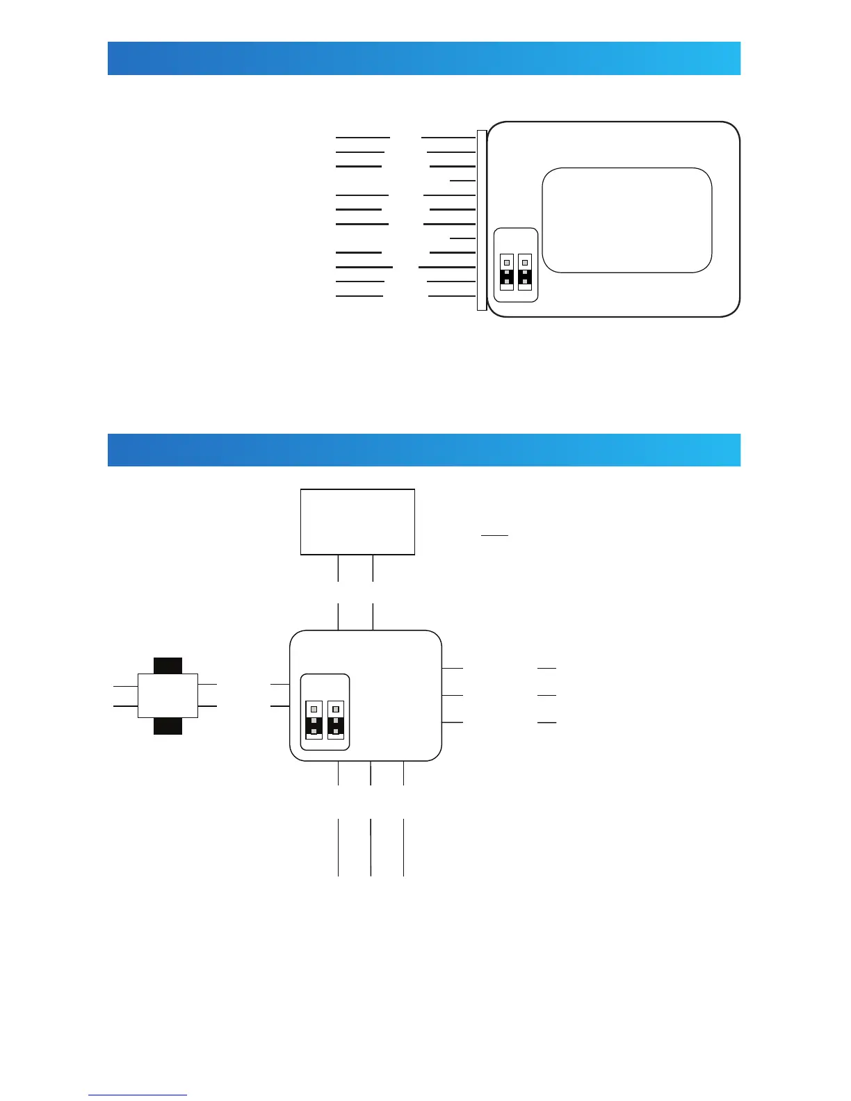
ELECTRICAL INSTALLATION
RELAY 2 N.O. contact
RELAY 2 N.C. contact
RELAY 2 COM contact
COM / N.O. (Act. Device input contact)
Power (-) 15 – 24 VAC/VDC
COM / N.O. (Act. Device input contact)
Power (+) 15 – 24 VAC/VDC
RELAY 1 COM contact
RELAY 1 N.O. contact
RELAY 1 N.C. contact
BLACK
RED
GRAY
GRAY
ORANGE
PURPLE
BROWN
GREEN
BLUE
YELLOW
JP11
4 JP2
JP
1
R
E
L
A
Y
1
R E L A Y 2
GRAY GRAY
GREEN YELLOW BLUE
(NC) (COM) (NO)
PURPLE (NC)
RED (COM)
BLACK (NO)
ORANGE
BROWN
NOTE : Unused wires must be insulated
to prevent damage. No voltage
should be applied to the gray wires
or damage to the unit will result.
MAGLOCK / ELECTRIC STRIKE
can either be a wet or dry output,
depending on jumper position
DOOR CONTROL
activation circuit at door control
Use blue and yellow for activation circuits requiring
a closed contact to activate the control.
observe polarity when
using DC power
15 – 24
VAC
 Loading...