75.5985.01 MS31 20200630 Page 3 of 4
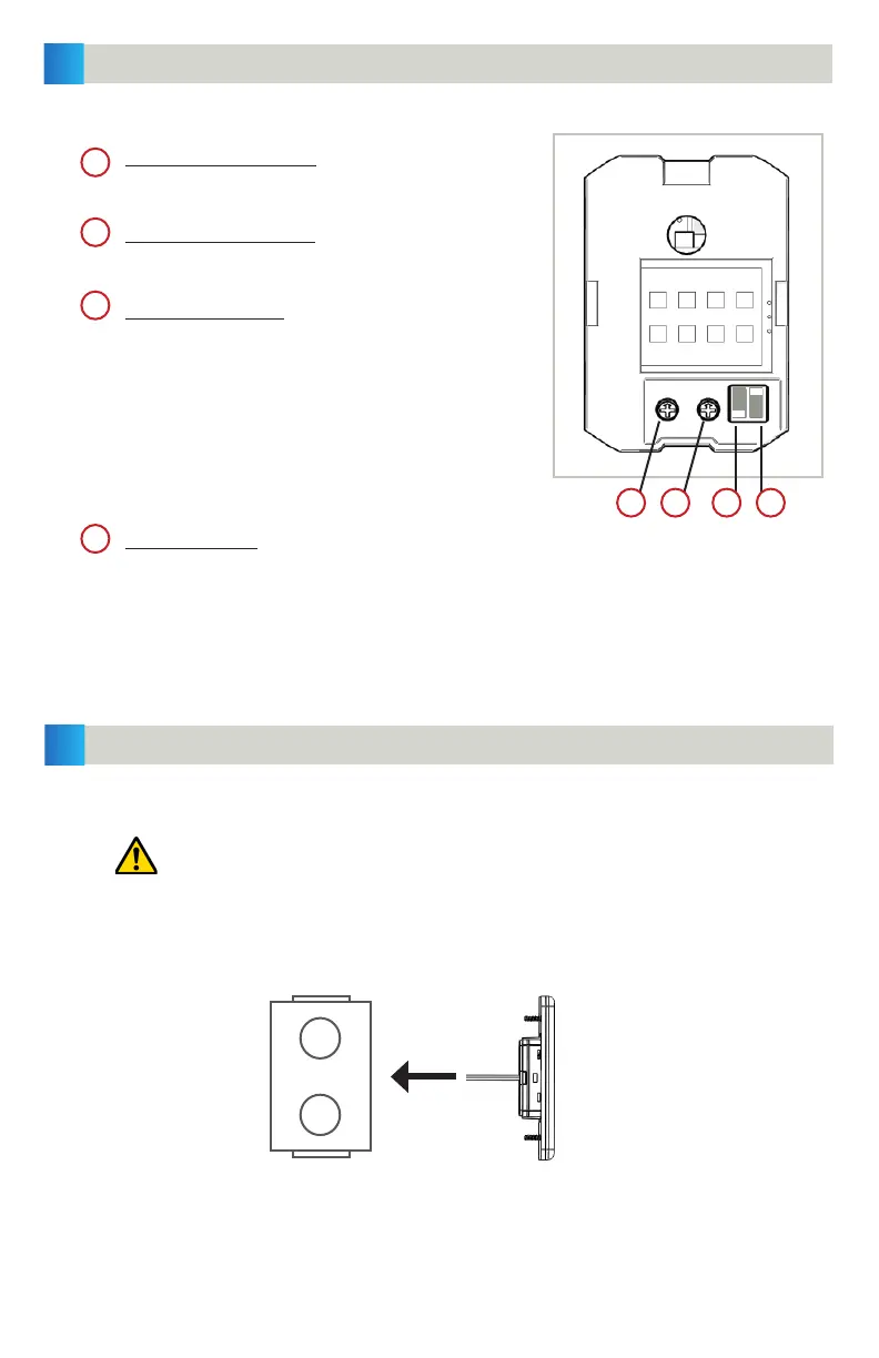
INSTALLATION
3
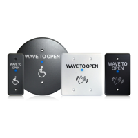
SET-UP
2
1. Install an electrical box.
If using a metal eletrical box, ensure that the sensor does not come in
contact with the box to avoid shorting the unit.
2. Clip the MAGIC SWITCH cube to the face plate.
3. Secure the face plate to the electrical box with the provided screws.
Four adjustments can be made to the sensor:
Sensitivity potentiometer: adjust detection field
from 4 to 24 inches (rotate clockwise to increase)
factory default: 4 inches (fully CCW)
Hold time potentiometer: adjust relay hold time
from 0.5 to 30 seconds (rotate clockwise to increase)
factory default: 0.5 sec (fully CCW)
Output Mode switch: determines Toggle mode or
Timer mode
- Toggle (switch up) = detection activates the relay
and the relay holds until a second detection
deactivates the relay (recommended for switch
applications)
- Timer (switch down, factory default) = detection
activates the relay for 0.5 to 30 seconds; relay will
hold as long as detection occurs
LED mode switch: determines if LED illuminates when in detection or when not in
detection
- switch up (factory default) = LED on when sensor is NOT in detection, LED off when in
detection
- switch down = LED on when sensor is is in detection, LED off when not in detection
gang box
(metal/plastic)
MAGIC SWITCH
assembly
1
21 3 4
2
3
4
Depending on the door installation, the weather-resistant foam gasket may be used.