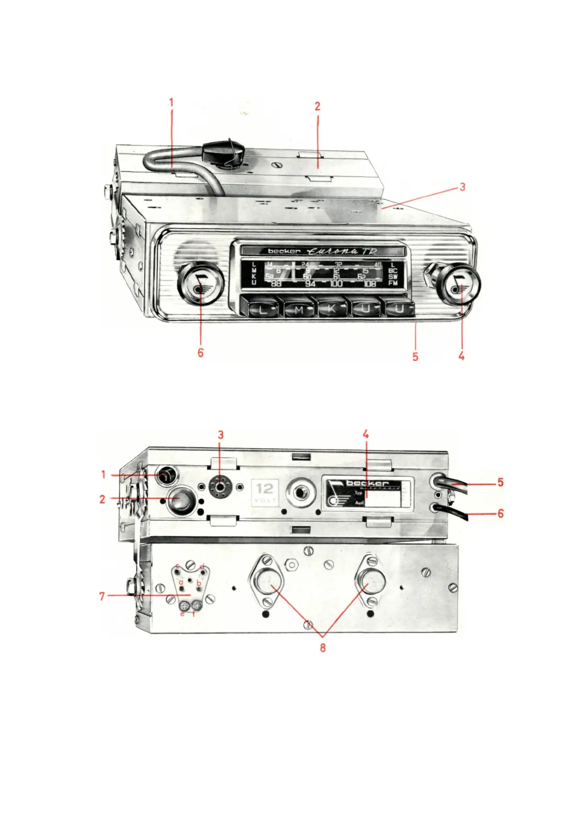
Fig. 1
1 connection cable between the device and LF section
2. LF part with end stage
3. receiver part
4. Manual tuning
5th hole for the adjustment of the antenna trimmer (below 750 mm seen against
device-back)
6. volume control, on-off (by rotation), tone control (in two stages, by -Zug to use)
Fig. 2
1. Antenna socket
2. plug (for connection Installation of turntable or tape recorders)
3. Ratio adjustment socket
4. Nameplate
5. connecting cable between the device and LF section
6. Power Cable
7. speaker connection plate (with two sockets for connecting any of a KW-adapter
"Reims 8" or an automatic Antenna e, f)
Explanatory note: A loudspeaker (5 Ω) between a-b connect. Two speakers (each 5 Ω) Explanatory note: A loudspeaker (5 Ω) between a-b connect. Two speakers (each 5 Ω) Explanatory note: A loudspeaker (5 Ω) between a-b connect. Two speakers (each 5 Ω) Explanatory note: A loudspeaker (5 Ω) between a-b connect. Two speakers (each 5 Ω)
between a-c and b-d
connect.
Before connecting a load to the socket e or f of the plastic plug must be removed
(by releasing the respective stud). The stud bolts are perpendicular to reach under
the sleeves e or f by the openings provided in the lid.
8. output transistors under the protection angle plate.
- 4 -
 Loading...