Product overview
Embedded PC 17
CPU basic module with 2 Ethernet RJ 45 connectors:
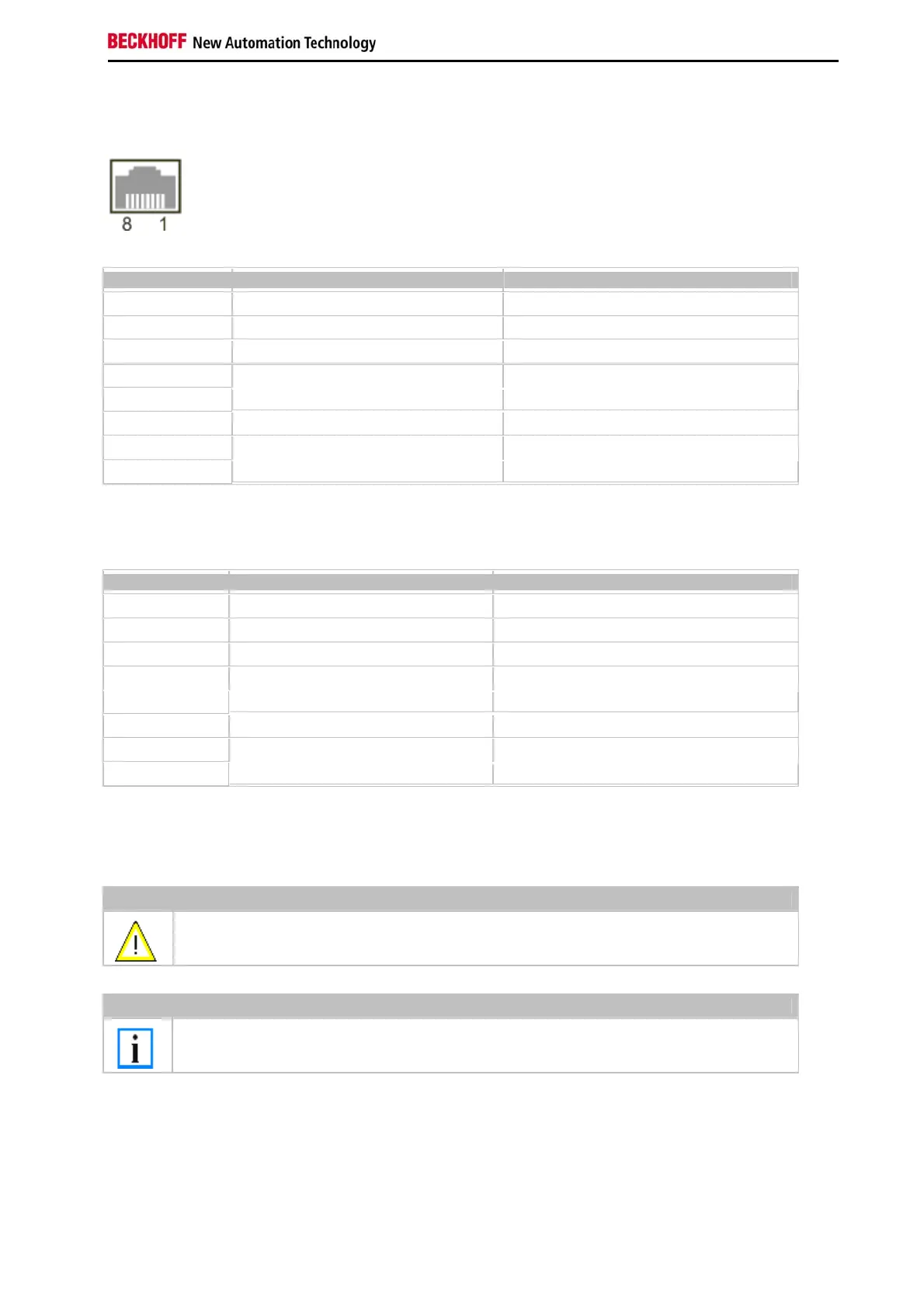
RJ 45 interface (socket):
Assignment of the RJ45-interface, Port 1:
PIN Signal Desciption
1 TD + Transmit +
2 TD - Transmit -
3 RD + Receive +
4
5
connected not used
6 RD - Receive -
7
8
connected not used
TD & RD are exchanged at the hubs or between two PCs.
Assignment of the RJ45 interface, Port 2:
PIN Signal Description
1 TD + Transmit +
2 TD - Transmit -
3 RD + Receive +
4
5
connected not used
6 RD - Receive -
7
8
connected not used
TD & RD are exchanged at the hubs or between two PCs.
Connection of the Ethernet ports:
Warning
The two Ethernet ports of a basic CPU module must not be connected to the same external switch!
Note
Only for use in LAN, not for connection to telecommunication circuits.
Schematic structure of the network components:
The CX9000 features two MAC blocks. The first one (MAC1) operates the network interfaces for the Ethernet ports.
The two outputs are connected via a switch. In this way a line structure can be configured as described below. From
an operating system perspective this represents a single connection. The second block (MAC2) operates the
extended PC104 bus. The second physical network connection is used to run the E-bus connection. (in version
CX900x-0xxx) The signals are connected to and FPGA. This unit converts the Ethernet signals to E-bus signals. So
EtherCAT terminals can be connected to the system.

 Loading...