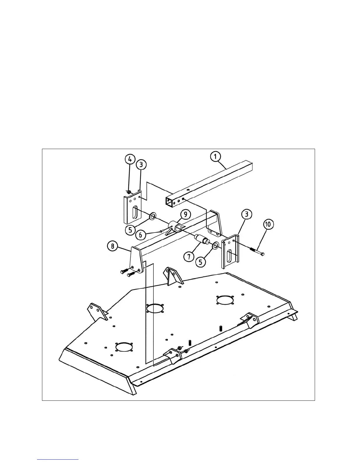
2. Insert the attaching pin (see #7, fig. 3) into the tube welded to the hitch (see #9, fig.
3). Place the shim washers (see #5, fig. 3) on either end of the attaching pin.
3. Place the two formed plates (see #3, fig. 3) on either end of the attaching pin (see
#7, fig. 3) with the bend facing outward.
4. With the wing arms down level with the mower decks, position the telescopic wing
arms (see #1, fig. 3) between the two formed plates (see #3, fig. 3). Attach them to
the bolts (see #10, fig. 3) provided.
5. Tighten the nuts (see #4, fig. 3) and bolts (see #10, fig. 3). Ensure after tightening
that the formed plates (see #3, fig. 3) move freely up and down over the attaching
pin (see #7, fig. 3).
6. Using the grease fitting on the hitch (see #6, fig. 3), grease the attaching pin and
formed plate.
OPERATION 14 BEFCO
C
YCLONE SUPER-FLEX OPERATOR’S MANUAL
Fig. 3 - Mowing unit assembly.


 To Next Page