side. This is done by removing the retaining bolt and sliding the wing frame in or out to
the desired position (see fig. 9). You may choose to drill holes for additional adjustment
positions.
As the wing units, the central unit is also assembled to the frame with telescopic arms
that are adjustable in several positions (see fig. 11 & 12).
Important: Always check PTO length when adjusting the deck overlap.
Leveling Flex Frame
The second pivot point is where the telescopic arms connect to the mowers. Each deck
has two pins, one in the front and one in the rear, nested between two stamped plates
with large slots. The plates are attached to each of the frame arms with three bolts. As
the mower floats over the ground, the slots allow it to follow the ground contour without
interference (see fig. 10).
It is best to make leveling adjustments with the tractor and mower on flat ground. Lower
all three mowing decks ensuring the hydraulic pressure from the tractor is completely
released.
The frame is level when all three decks have each of their two pins in approximately the
same position in relation to the slots in the stamped plates which are attached to the
telescopic arms (see fig. 9).
Operating the machine with the hitch set too high or low will reduce float capability of
the decks and could result in scalping or an uneven cut. If the front position is down and
the rear position is up then the tractor hitch point is too low. If the front position is up and
the rear position is down then the tractor hitch point is too high.
OPERATION 23 BEFCO
C
YCLONE SUPER-FLEX OPERATOR’S MANUAL
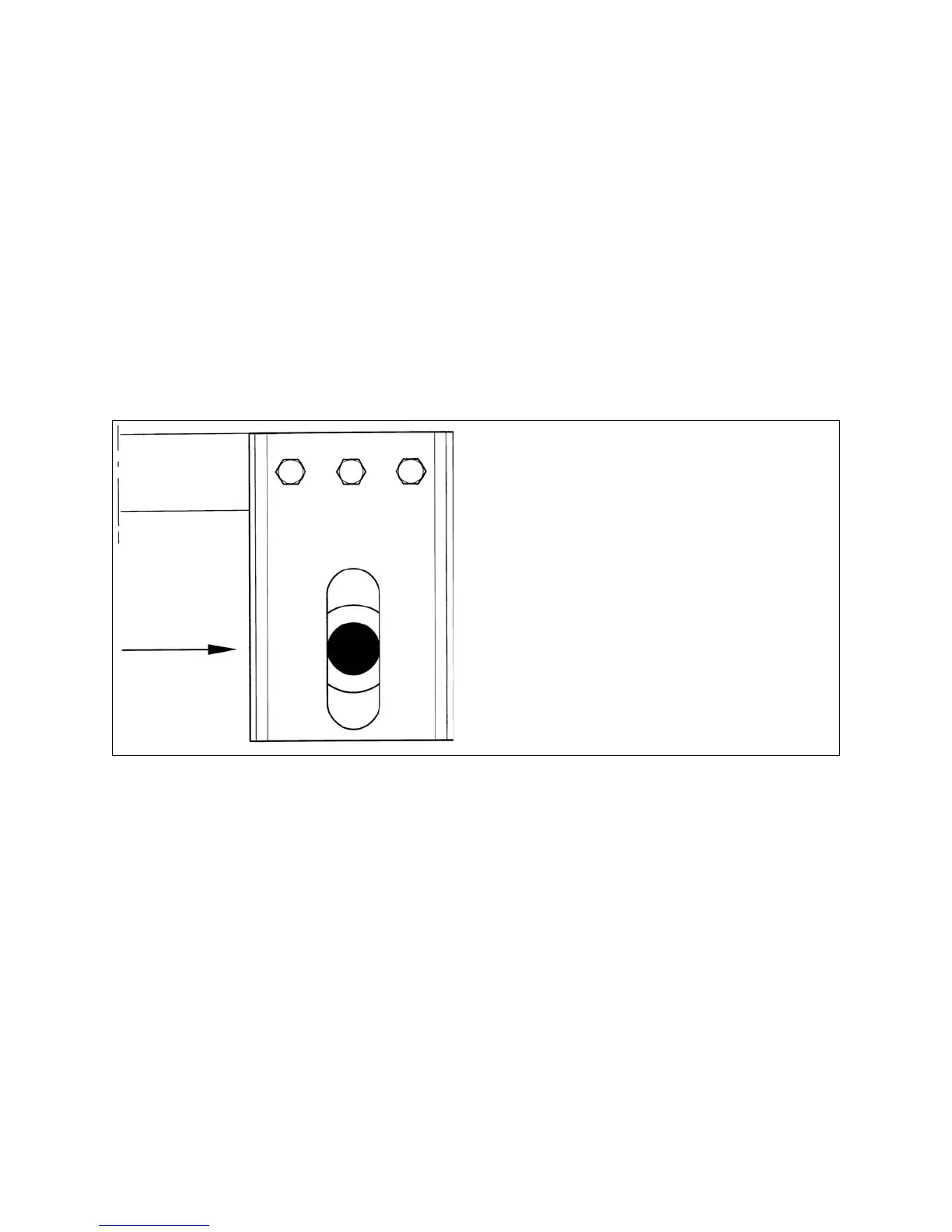
Fig. 10
The arrow shows the pin centered
in the rectangular plates bolted to
the end of the telescopic arm.
Both the front and rear arm must be in
this position.
 Loading...