12 13Quick Start Guide
ABACUS
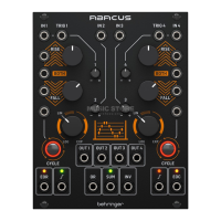
ABACUS Controls
(12) CHANNEL 2 ATTENUVERTER –
Use this control to attenuate
(CW) or invert (CCW) voltages
fed to Channel 2 input on socket
3 or the internally generated
voltage in the range -10 V to
+ 10 V.
(13) CHANNEL 3 ATTENUVERTER –
Use this control to attenuate
(CW) or invert (CCW) voltages
fed to Channel 3 input on socket
4 or the internally generated
voltage in the range -5 V to
+ 6 V.
(14) CHANNEL 4 BOTH CV INPUT –
Accepts a voltage in the range
+/- 8 V. A positive voltage will
exponentially decrease the
total Rise/Fall time, until the
minimum is reached; a negative
voltage exponentially increases
it until it reaches maximum.
(15) CHANNEL 1 FALL CV INPUT –
Allows CV control of the Fall
function, in conjunction with
control 16. Accepts voltages
in the range +/- 8 V. Positive
voltages increase the Fall time
until the maximum is achieved;
negative voltages decrease it
until it reaches minimum.
(16) CHANNEL 1 FALL TIME –
Use this control to set the
Fall time. See table below for
maximum times according
to dierent settings. Can be
modulated further by feeding
a CV to socket 15.
(17) CHANNEL 4 FALL TIME –
Use this control to set the
Fall time. See table below for
maximum times according
to dierent settings. Can be
modulated further by feeding
a CV to socket 18.
(18) CHANNEL 4 FALL CV INPUT –
Allows CV control of the Fall
function, in conjunction with
control 16. Accepts voltages
in the range +/- 8 V. Positive
voltages increase the Fall time
until the maximum is achieved;
negative voltages decrease it
until it reaches minimum.
(19) CHANNEL 1 CYCLE TRIGGER –
Allows an external positive
going gate or trigger of +2.5 V
or more to trigger Channel 1’s
Cycle function.
(20) CHANNEL 1 ATTENUVERTER –
Use this control to attenuate
(CW) or invert (CCW) the
output of Channel 1 after
Rise/Fall processing. Does not
pass internal voltage unless
processing is taking place.
(21) CHANNEL 4 ATTENUVERTER –
Use this control to attenuate
(CW) or invert (CCW) the
output of Channel 1 after
Rise/Fall processing. Does not
pass internal voltage unless
processing is taking place.
(22) CHANNEL 4 CYCLE TRIGGER –
Allows an external positive
going gate or trigger of +2.5 V
or more to trigger Channel 4’s
Cycle function.
(23) CHANNEL 1 RESPONSE –
Use this control to vary the
response of Channel 1 from
logarithmic through linear to
exponential. See table below.
(24) CHANNEL 4 RESPONSE –
Use this control to vary the
response of Channel 4 from
logarithmic through linear
to exponential. See table below.
(25) CHANNEL 1 CYCLE – Use this
button to initiate cycling of
Channel 1; Rise and Fall will
cycle until button is pressed
again to stop the cycle. Button
is illuminated when cycling.
Button ashes when Cycle is
externally triggered via socket
19. Internal Cycle takes priority
over external trigger.
(26) CHANNEL 1 OUTPUT –
Outputs the processed voltage
from Channel 1.
(27) CHANNEL 2 OUTPUT –
Outputs the processed voltage
from Channel 2.
(28) CHANNEL 3 OUTPUT –
Outputs the processed voltage
from Channel 3.
(29) CHANNEL 4 OUTPUT –
Outputs the processed voltage
from Channel 4.
(30) CHANNEL 4 CYCLE – Use this
button to initiate cycling of
Channel 4; Rise and Fall will
cycle until button is pressed
again to stop the cycle.
Button is illuminated when
cycling. Button ashes when
Cycle is externally triggered via
socket 22. Internal cycle takes
priority over external trigger.
(31) CHANNEL 1 END OF
RISE OUTPUT – Outputs a
+ 9 V voltage at the top of the
Rise function, indicated by the
associated LED, which continues
active until the end of the
Fall cycle.
(32) CHANNEL 1 UNITY OUTPUT –
Outputs a 0 - +10 V voltage
following the Rise/Fall
functions when Channel 1 is
cycling; otherwise follows the
channel input unaected by the
attenuverter. LED shows green
for a positive voltage, red for a
negative one.