14 15Quick Start Guide
ABACUS
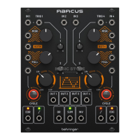
ABACUS Controls
(33) OR OUTPUT – Outputs the
result of an analog OR function
based on the setting of the
attenuverters for Channels
1 – 4 (controls 12, 13, 20, 21).
Channels 1 and 4 need an
external voltage to be included.
(34) SUM OUTPUT – Outputs a
summed voltage in the range
+/- 10 V based on the settings
of the attenuverters for
Channels 1 – 4 (controls 12,
13, 20, 21). LED shows green
for a positive voltage, red for a
negative one. Channels 1 and 4
need an external voltage to
be included.
(35) INVERTED SUM OUTPUT –
Outputs the inversion of the
Sum output 34.
(36) CHANNEL 4 UNITY OUTPUT –
Outputs a 0 - +10 V voltage
following the Rise/Fall
functions when Channel 4
is cycling; otherwise follows the
channel input unaected by the
attenuverter. LED shows green
for a positive voltage, red for a
negative one.
(37) CHANNEL 4 END OF
CYCLE OUTPUT - Outputs a
+ 9 V voltage at the end of the
Rise/Fall cycle, indicated by the
associated LED.
(ES) Paso 2: Controles
(1) CHANNEL 1 CV INPUT –
Acepta voltajes variables en
el rango de +/- 10 V para su
procesado por el canal 1. Si no
hay ningún voltaje presente,
el Abacus usará un voltaje
auto-generado de
aproximadamente +10 V.
(2) CHANNEL 1 TRIGGER INPUT –
Acepta cualquier señal de
puerta o disparador entrante
positiva que supere los + 2.5 V.
Esta señal hace que la función
Rise/Fall sea activada.
(3) CHANNEL 2 CV INPUT –
Acepta voltajes en el rango
de +/- 10 V para atenuarlos/
invertirlos (“attenuverting”)
por el control 20.
(4) CHANNEL 3 CV INPUT –
Acepta voltajes en el rango
de +/- 10 V para atenuarlos/
invertirlos (“attenuverting”)
por el control 21.
(5) CHANNEL 4 TRIGGER INPUT –
Acepta cualquier señal de
puerta o disparador entrante
positiva que supere los + 2.5 V.
Esta señal hace que la función
Rise/Fall sea activada.
(6) CHANNEL 4 CV INPUT –
Acepta voltajes variables en
el rango de +/- 10 V para su
procesado por el canal 4. Si no
hay ningún voltaje presente,
el Abacus usará un voltaje auto-
generado de aproximadamente
+10 V.
(7) CHANNEL 1 RISE CV INPUT –
Permite el control CV de la
función Rise junto con el
control 8. Acepta voltajes en el
rango de +/- 8 V. Los voltajes
positivos aumentan el tiempo
del Rise (incremento) hasta
que es alcanzado el máximo;
los voltajes negativos lo
reducen hasta que es alcanzado
el mínimo.
(8) CHANNEL 1 RISE TIME – Use
este control para ajustar el
tiempo del incremento o Rise.
Vea en la tabla de abajo los
tiempos máximos obtenidos
de acuerdo con los diferentes
ajustes. Puede modular esto
aún más dando entrada a una
señal CV en la toma 7.
(9) CHANNEL 4 RISE TIME –
Use este control para ajustar el
tiempo del incremento o Rise.
Vea en la tabla de abajo los
tiempos máximos obtenidos
de acuerdo con los diferentes
ajustes. Puede modular esto
aún más dando entrada a una
señal CV en la toma 10.
(10) CHANNEL 4 RISE CV INPUT –
Permite el control CV de la
función Rise junto con el
control 9. Acepta voltajes en el
rango de +/- 8 V. Los voltajes
positivos aumentan el tiempo
del Rise (incremento) hasta que
es alcanzado el máximo;
los voltajes negativos lo
reducen hasta que es alcanzado
el mínimo.
(11) CHANNEL 1 BOTH CV INPUT –
Acepta un voltaje en el rango
de +/- 8 V. Un voltaje positivo
reducirá de forma exponencial
el tiempo Rise/Fall total,
hasta que llegue al mínimo;
un voltaje negativo aumentará
exponencialmente ese tiempo
hasta llegar al máximo.
(12) CHANNEL 2 ATTENUVERTER –
Use este control para atenuar
(derecha) o invertir (izquierda)
los voltajes enviados a la
entrada del canal 2 en la
toma 3 o el voltaje generado
internamente en el rango de
-10 a + 10 V.
(13) CHANNEL 3 ATTENUVERTER –
Use este control para atenuar
(derecha) o invertir (izquierda)
los voltajes enviados a la