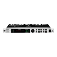
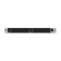
12 13FEEDBACK DESTROYER PRO FBQ2496 Quick Start Guide
FEEDBACK DESTROYER PRO FBQ2496 Controls
(1) LEVEL METER – The LEVEL METER lets
you monitor the input level. Eight LEDs are
available per channel. If the Clip LED lights
up, digital distortion may occur on FBQ2496’s
input. In this case, reduce the input level.
(2) LEARN button – A quick tap on the LEARN
button (LED lights up) gets you into the LEARN
mode. The FBQ2496 will immediately start
looking for critical frequencies and will deploy
as many Single-Shot lters as necessary
(ofcourse, music or noise has to be present in
the room for this to work).
(3) PANIC – If unexpected feedback starts
occurring during a performance, pressing the
PANIC button can help. As long as the button
is kept pressed (for a maximum of 1 second),
your FBQ2496 rapidly searches for feedback
frequencies and suppresses them.
(4) SPEECH – Pressing the SPEECH button
increases the sensitivity of feedback
suppression; the FBQ2496 recognizes critical
frequencies sooner and deploys a lter that
cuts in appropriately.
(5) FREEZE – Once a particularly good FBQ2496
setting is achieved, you can keep this setting
by pressing the FREEZE button. All Single-Shot
and automatic lters are kept at their settings
until you press FREEZE again.
(6) FILTER LIFT – The so-called “Filter Lifting
Time” informs you about how long an
adjusted automatic lter can remain inactive
before its values are reset again. You can set
this time by rst briey pressing the FILTER
LIFT button and then turning the wheel.
Thefollowing time lengths are available:
0min, 1 min, 5 min, 10 min, 30 min, 60min.
(7) RESET – If you briey press the RESET button,
all automatically set lters are erased. Ifyou
keep the RESET button pressed longer,
Single-Shot lters are erased as well. In PEQ
mode, briey pressing the RESET button
erases the selected lter. Keeping the
RESET button pressed longer erases all the
parametric lters all at once.
(8) STATUS DISPLAY – The FBQ2496 features a
total of 40 lters, i.e. 20 lters per channel.
They can be monitored and controlled on the
STATUS DISPLAY.
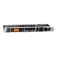
(1) (4)(2) (5)(3) (8) (9) (12)(10) (13)(11)
(6) (7) (16) (17) (18)(14) (15)
(20)
(19)
(21) (22)
(24) (23)
(9) LED DISPLAY – The three-digit numeric
display indicates the absolute value of the
parameter you are modifying.
(10) GAIN – In the PEQ mode, the GAIN button lets
you adjust lter gain in dB (from +15 dB to
-15dB in 0.5-dB increments, and from -16 dB
to -36 dB in 1-dB increments). The dB value
set using the wheel is shown in the display.
(11) PEQ – After keeping the PEQ button pressed
for a few moments (the LED on the PEQ button
blinks), use the wheel to set the number
of parametric lters. They start with the
lter number 20 and can go down to lter
number1, step by step. At the same time,
thealready set Single-Shot lters are shown.
If you only briey press the PEQ button
(theLED on the PEQ button is lit), any lter
can be called up using the wheel. The number
of the selected lter is shown in the display,
and the corresponding lter LED blinks.
Amplication, bandwidth and mid frequency
parameters can now be shown.
(12) FREQUENCY – When the FBQ2496 is in the
PEQ mode (the LED on the PEQ button is lit),
themid frequency of each individual lter can
be set. To modify the mid frequency, press the
FREQUENCY button. The frequency range can
vary from 20 Hz to 20 kHz.
(13) LEFT-RIGHT – The LEFT-RIGHT button lets
you select the channels you wish to edit.
(14) BANDWIDTH – Use the BANDWIDTH button
to set the bandwidth (Q-factor/quality) of the
selected parametric lter. The adjustable lter
quality encompasses a range from 1/60th of
an octave up to 10 octaves. The FBQ2496 has
to be in PEQ mode (the LED on the PEQ button
is lit).
(15) BYPASS – Keeping the BYPASS button pressed
for a few moments activates the hard bypass.
The unit’s input is directly routed to the
output and the lters are bypassed.
(16) MIDI – Simultaneously pressing BANDWIDTH
and BYPASS gets you into the MIDI menu
(bothbutton LEDs are lit).
(17) WHEEL – WHEEL is a continuous rotary
control. Use it to make adjustments to the
selectedparameter.
(18) POWER
(19) The mains connection is established using
a cable with an IEC mains connector.
Anappropriate mains cable is included.
(20) You can replace fuses at the FUSESWITCH
of the FBQ2496. Alwaysreplace fuses with
the same type.
(21) The FBQ2496 features a complete set
of MIDI functions. In addition to the
usual MIDI IN and MIDI OUT ports,
theMIDITHRU allows you to loop through
MIDI data.
(22) Use the OPERATING LEVEL switch
to change from home recording level
(-10dBV) to studio level (+4 dBu), andvice
versa. The level meters are adapted
automatically to the selected nominal
level, so that the FEEDBACK DESTROYER
PRO will always work in its optimum
operating range.
(23) INPUT LEFT/RIGHT – These are the
balanced inputs of your FBQ2496. They are
laid out as ¼" TRS and XLR connectors.
(24) OUTPUT LEFT/RIGHT – Both of the
FBQ2496 outputs are also laid out as
balanced ¼" TRS and XLR connectors.
For more details on the full functionality
of this product, see the product page
on behringer.com and download the
full manual.
(EN) Controls

 Loading...