9
E
The mains connection of the ULTRA-CURVEPRO is made by using a mains cable and a standard IEC
receptacle. It meets all of the international safety certification requirements. Please make sure that all units
have a proper ground connection.
+ Before you connect your ULTRA-CURVEPRO to the mains, please make sure that your local
voltage matches the voltage required by the unit! (see chapter 5 for details)
+ Please ensure that only qualified persons install and operate the ULTRA-CURVEPRO. During
installation and operation the user must have sufficient electrical contact to earth. Electro-
static charges might affect the operation of the ULTRA-CURVEPRO!
As a standard the audio inputs and outputs on the BEHRINGER ULTRA-CURVEPRO are fully balanced. If
possible, connect the unit to other devices in a balanced configuration to allow for maximum interference
immunity.
1.3 Control elements
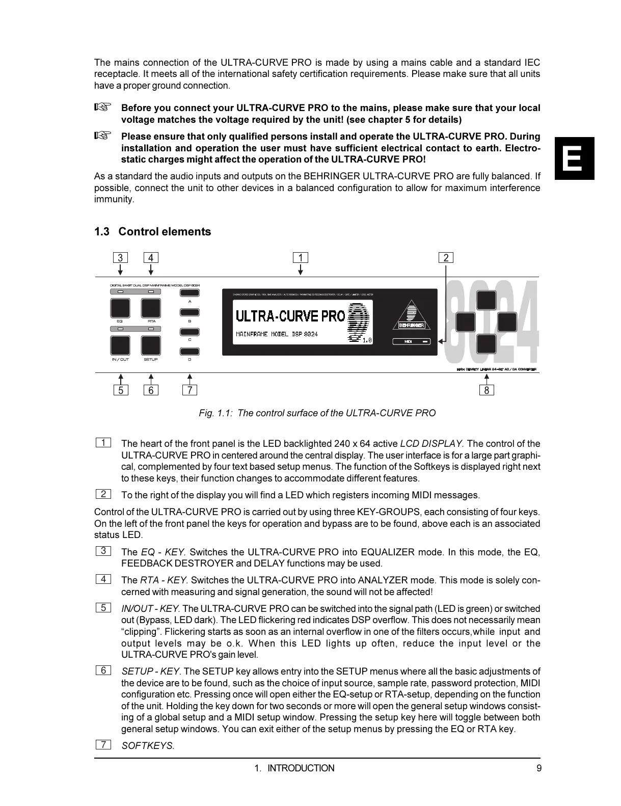
Fig. 1.1: The control surface of the ULTRA-CURVEPRO
1
The heart of the front panel is the LED backlighted 240 x 64 active LCD DISPLAY. The control of the
ULTRA-CURVEPRO in centered around the central display. The user interface is for a large part graphi-
cal, complemented by four text based setup menus. The function of the Softkeys is displayed right next
to these keys, their function changes to accommodate different features.
2
To the right of the display you will find a LED which registers incoming MIDI messages.
Control of the ULTRA-CURVEPRO is carried out by using three KEY-GROUPS, each consisting of four keys.
On the left of the front panel the keys for operation and bypass are to be found, above each is an associated
status LED.
3
The EQ - KEY. Switches the ULTRA-CURVEPRO into EQUALIZER mode. In this mode, the EQ,
FEEDBACK DESTROYER and DELAY functions may be used.
4
The RTA - KEY. Switches the ULTRA-CURVEPRO into ANALYZER mode. This mode is solely con-
cerned with measuring and signal generation, the sound will not be affected!
5
IN/OUT - KEY. The ULTRA-CURVEPRO can be switched into the signal path (LED is green) or switched
out (Bypass, LED dark). The LED flickering red indicates DSP overflow. This does not necessarily mean
clipping. Flickering starts as soon as an internal overflow in one of the filters occurs,while input and
output levels may be o.k. When this LED lights up often, reduce the input level or the
ULTRA-CURVEPRO's gain level.
6
SETUP - KEY. The SETUP key allows entry into the SETUP menus where all the basic adjustments of
the device are to be found, such as the choice of input source, sample rate, password protection, MIDI
configuration etc. Pressing once will open either the EQ-setup or RTA-setup, depending on the function
of the unit. Holding the key down for two seconds or more will open the general setup windows consist-
ing of a global setup and a MIDI setup window. Pressing the setup key here will toggle between both
general setup windows. You can exit either of the setup menus by pressing the EQ or RTA key.
7
SOFTKEYS.
1. INTRODUCTION

 Loading...