12 13ULTRAGAIN PRO MIC2200 Quick Start Guide
ULTRAGAIN PRO MIC2200 Controls
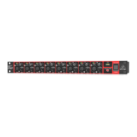
Rear panel elements of the ULTRAGAIN PRO
(1) (4)
(2) (5) (7)(3) (6) (8) (11) (12) (14)(9) (13)
(10) (15)
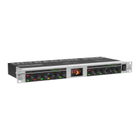
Control elements on the front panel
(16)
(17)
(19) (18)
(EN) Controls
(1) This +48 V switch activates the +48 V phantom power
circuit that uses the signal leads to supply condenser
microphones with the required operatingvoltage.
(2) Use the MIC/LINE switch to toggle between
MICandLINE modes. When the switch is pressed,
theunit works in MIC mode (now you can press the
+48V switch if required; in LINE mode this function
isdisabled).
(3) The MIC GAIN control is enabled in MIC mode only and
allows for applying gain from 10 to 60 dB to the input
signal. In view of the extremely high gain levels that
can be applied, you should verify that the gain control
is properly set before you power up the unit. Incase
of doubt, set the control fully counter-clockwise,
andstart from there slowly raising the gain. Highgain
settings and the resulting levels can damage
subsequent devices.
(4) The CLIP LED signals that a level of at least +18 dBu
is present after the microphone amp stage. With too
high a level the CLIP LED warns you to reduce the gain
with the MIC GAIN control, so as to avoid distortion
caused by overloading. During normal operation,
theLED should not light up at all.
(5) With the PHASE REV. switch the input signal is
reversed in phase by 180°. This function is available
both in MIC and LINE modes.
(6) When the high-pass lter is switched on (LO CUT
switch pressed), theFREQUENCY control denes
the lter’s cut-o frequency. With a setting range
from 12to 320 Hz the lter’s main task is to eliminate
bottom-end rumble noise, etc.
(7) The LO CUT switch activates/deactivates the
high-passlter.
(8) The FREQUENCY control is used to select the
frequency to be modied. Please note that the
frequency range can be lowered/raised with the
switches x0.1 and x10. In this way, you can process
the entire audio range between 10 Hz and 20 kHz.
Withboth switches out, the FREQUENCY control can
beswept over a range from 100 Hz to 2 kHz.
(9) The x 0.1 switch lowers the working range of the
FREQUENCY control to 10 - 200 Hz, so that you can
process the bass end of the audio spectrum.
(10) The x 10 switch raises the working range of the
FREQUENCY control to 1 - 20 kHz, so that you can
process the treble end of the audio spectrum.
(11) The BANDWIDTH control determines the slope
orquality of the lter. Bandwidth ranges from
0.03(Q=43) to 2 octaves (Q = 0,67).
(12) With the LEVEL control you can set the amount of level
reduction/gain applied to the lter. The setting range
is from -15 to +15 dB.
(13) The EQ IN/OUT switch activates/deactivates the
parametric EQ. Please switch the EQ o unless you
need it for your specic audio application.
(14) The OUTPUT control raises/lowers the output level
ofthe device by a maximum of 20 dB (+/- 20 dB).
Withthe control in mid-travel position, nolevel
change is applied. Available both in MIC and
LINEmodes.
(15) The OUTPUT LEVEL LED chain displays the output
level within a range from -30 to +18 dB. The display
isreferenced to a level of +4 dBu.
(16) FUSE HOLDER / VOLTAGE SELECTOR.
(17) MAINS CONNECTION. Use the enclosed power cord
to connect the unit to the mains. Please also note the
instructions given in the “Installation” chapter.
(18) AUDIO IN. These are the audio inputs of your
ULTRAGAIN PRO. The XLR connector is the
common mic/line input. The line input is based on
jackconnection.
(19) AUDIO OUT. These are the audio outputs of your
ULTRAGAIN PRO. Matchingphone jack and XLR
connectors are wired in parallel.
Check Out behringer.com for Full Manual
 Loading...