26
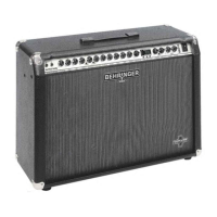
ULTRATWIN GX212
Fig. 5.2: Wiring of a stereo headphones 1/4" plug
5.2.1 Loudspeaker connection
Your GX212 features two speaker jacks that allow you to hook up supplementary speakers. Optimum adaptation
is ensured with 8 W loudspeakers. Use the INTERNAL OFF switch on the rear panel of the GX212 to activate
the external speakers connected to your ULTRATWIN.
You can also connect speakers with lower impedances. However, this could trigger the power stage protective
circuitry on your GX212. Never use speakers with an impedance of less than 4 W. As the connected impedance
goes up, the maximum power output will drop in proportion to the resistance connected.
5.3 MIDI connection
The MIDI standard (Musical Instruments Digital Interface) was developed in the early 80s to enable electronic
musical instruments of different makes to communicate with each other. Over the years the range of MIDI
applications has constantly expanded, and today it is completely normal to network entire recording studios
using the MIDI standard.
At the heart of this network we find a computer loaded with a sequencer software that controls not only the
keyboards but also effects and other peripheral devices. In such a studio you could control your ULTRATWIN
in real time from a computer. In particular, when playing live gigs you can use a MIDI footcontroller to control
both the effect parameters and channel/effect changes on your ULTRATWIN.
The MIDI connector on the rear of your ULTRATWIN is an internationally standardized 5-pin DIN jack. To
connect your ULTRATWIN to other MIDI equipment, you need a dedicated MIDI cable, which is commercially
available in various lengths. However, you can solder your own cables using 2-conductor shielded cables (e.g.
microphone cables) and two rugged 180° DIN plugs: pin 2 (center) = shield; pins 4 and 5 (right and left of pin 2)
= internal conductor; pins 1 and 3 (the outer pins) are not used. MIDI cables should not exceed a length of 15
meters.
+ Make sure that pin 4 is connected to pin 4, and pin 5 to pin 5 on both plugs.
MIDI IN: receives MIDI controller information. The receiving channel can be set with the buttons UP and DOWN.
On = Omni, i.e. MIDI data are received and processed on all channels (see section 3.2).
6. APPENDIX
6.1 Preset list
Table 6.1 on the next two pages provides you with information on effect numbers and names, parameter types
and ranges as well as factory default settings.
6. APPENDIX
 Loading...

