7
ULTRAVOICE DIGITAL VX2496
3. RECORDING WITH THE ULTRAVOICE DIGITAL
+ To avoid coloring the character of the sound, do not
set the threshold too low when using the opto
de-esser. When the threshold is set at its optimal
value, the effect should only be recognizable by
direct comparison to the unprocessed signal using
the IN/OUT button.
Use the MASTER FADER to match the output signal level
to the input sensitivity of the following device (e.g. your
DAT or hard disk recorder).
+ Start by tuning the master fader right down and
increase it slowly to the desired level. If you start
with too high a level, you risk overloading the inputs
of the devices that follow!
The six OUTPUT LEVEL LEDs show the level of the output
over a -10 to +15 dB range. Ensure that the output level
does not go into overload otherwise the signal at the
DIG OUT output will be too high and cause distortion.
Use the POWER button to turn on the ULTRAVOICE DIGITAL.
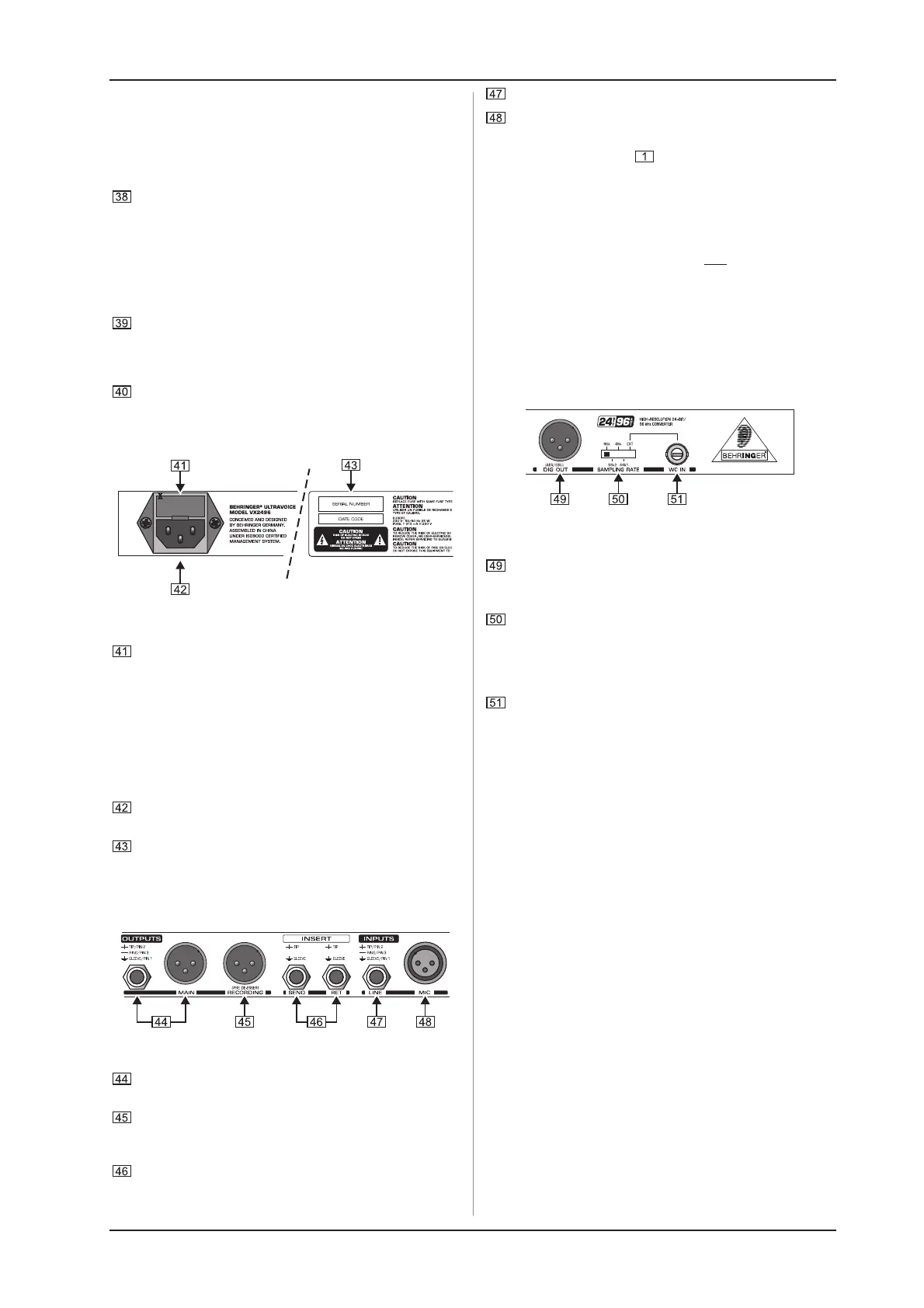
2.6 Rear panel connectors
Fig. 2.6: Mains connector and fuse holder
FUSE HOLDER/VOLTAGE SETTING. Before connecting the
unit to the mains, ensure that the voltage setting matches
your local voltage. A blown fuse should only be replaced
by a fuse of the same type and rating. On some units, the
fuse holder can be switched to one of two positions, i.e.
230 V and 120 V.
+ Should you desire to operate the unit outside Europe
at 120 V, a higher fuse rating is required (see
chapter 1.1).
The mains connection is on an IEC receptacle. An
appropriate power cord is included.
SERIAL NUMBER. Please take the time to complete and
return the warranty card within 14 days after the date of
purchase to benefit from our extended warranty. Or simply
register online at www.behringer.com. The serial number
needed for the registration is located at the top of the unit.
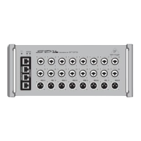
Fig. 2.7: ULTRAVOICE DIGITAL connections
These are the MAIN outputs of the ULTRAVOICE DIGITAL
on balanced XLR and 1/4" TRS jacks.
The XLR RECORDING output is for connection to a DAT
recorder, hard disk recorder or similar device and is sourced
pre de-esser.
This is the INSERT section with two 1/4" mono jacks as
SEND and RETURN for connecting an additional effects
device. The signal is sourced post low-cut filter of the
input stage.
The LINE input is on a balanced 1/4" TRS jack.
This is the balanced XLR connector for a microphone (MIC)
or line source.
+ When the Line key is pressed, XLR and the jack
connector are connected in parallel. If one line
signal is fed into both inputs at the same time, the
overall level of the output signal becomes lower,
and both signals are mixed with one another in the
same ratio.
+ Please avoid connecting a mic and a line-level signal
(CD player, sound card) to the input of your VX2496
at the same time. The low impedance of the
microphone would make the line signal barely
audible. Additionally, this could also damage the mic.
2.7 Digital AES/EBU output and
wordclock option
Fig. 2.8: The ULTRAVOICE DIGITAL digital interface
The digitally converted audio signal of the
ULTRAVOICE DIGITAL appears at the DIG OUT
(AES/EBU) output.
Use the SAMPLING RATE switch to select the sampling
rate at which the VX2496 analog signal is converted. You
can choose a sample rate frequency of 44.1, 48, 88.2 or
96 kHz. If you want to lock to an external wordclock, the
SAMPLING RATE switch should be set to EXT.
Wordclock for synchronization of the VX2496 can be fed
from an external device into the WC IN input. This connector
is a BNC coaxial jack and is only active when the SAMPLING
RATE switch is set to EXT.
The ULTRAVOICE DIGITAL VX2496 features a 24-bit/96 kHz
A/D converter with digital AES/EBU output. This allows you to
record the digital output direct onto a digital medium without the
need of an external A/D converter. Thus the ULTRAVOICE DIGITAL
can be seamlessly integrated into a hard disk recording system.
When several digital devices are integrated into a digital
recording system with, for instance, a digital mixing console, all
the digital devices must be synchronized to a common wordclock
signal. For this reason the VX2496 has a wordclock input which
enables it to be locked to an external device. It supports all
sampling rates from 32 to 96 kHz.
3. RECORDING WITH THE
ULTRAVOICE DIGITAL
When recording with the ULTRAVOICE DIGITAL, you should
strive to achieve as natural a sound as possible at the best
possible quality. During the mix the signal can then be given any
required special treatment, with the original recorded signal
always remaining pure.
1) Set an appropriate input level using the discrete vintage
input stages GAIN control.
2) Be sure to do everything possible to achieve the best sound
before it reaches the ULTRAVOICE DIGITAL. This includes
being especially careful to find the optimal position for the
microphone and ensuring that the surrounding acoustics
enhance the sound in the desired fashion.
Then, turn all the ULTRAVOICE DIGITAL controls off to
initialize the dry signal.
 Loading...