12 13XENYX QX1202USB/QX1002USB Quick Start Guide
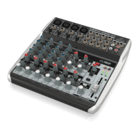
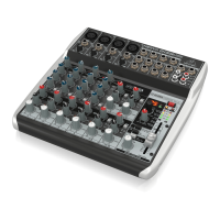
XENYX QX1202USB/QX1002USB Controls
(EN) Step 2: Controls
This chapter describes the various control elements
of your mixing console. All controls, switches and
connectors will be discussed in detail.
(1) MIC – Each mono input channel oers a
balanced microphone input via the XLR
connector and also features switchable
+48V phantom power supply for condenser
microphones. The XENYX preamps provide
undistorted and noisefree gain as is typically
known only from costly outboard preamps.
(2) LINE IN – Each mono input also features
a balanced line input on a ¼" connector.
Unbalanced devices (mono jacks) can also be
connected to these inputs. Please remember
that you can only use either the microphone
or the line input of a channel at any one time.
You can never use both simultaneously!
(3) GAIN – Use the GAIN control to adjust the
input gain. This control should always be
turned fully counterclockwise whenever you
connect or disconnect a signal source to one
of the inputs.
(4) EQ – All mono input channels include a
3-band equalizer. All bands provide boost
or cut of up to 15 dB. In the central position,
theequalizer is inactive.
(5) LOW CUT – In addition, the mono channels
are equipped with a steep LOW CUT
lter designed to eliminate unwanted
low-frequency signalcomponents.
(6) FX – FX sends enable you to feed signals via
a variable control from one or more channels
and sum these signals to a bus. Thebus
appears at the console’s FX send output
and can be fed from there to an external
eects device. The return from the eects
unit is then brought back into the console
on the stereo channels. Each FX send is
mono and features up to +15 dB gain. In the
QX1002USB/QX1202USB, the FX send is routed
directly to the built-in eects processor.
Tomake sure that the eects processor
receives an input signal, youshouldn’t turn
this control all the way to the left (-∞).
(7) PAN – The PAN control determines the
position of the channel signal within
the stereo image. This control features a
constant-power characteristic, whichmeans
the signal is always maintained at a
constant level, irrespective of position in the
stereopanorama.
(8) LEVEL – The LEVEL control determines the
level of the channel signal in the main mix.
(9) CLIP – The CLIP LED’s of the mono channels
illuminate when the input signal is driven
too high, which could cause distortion. Ifthis
happens, use the GAIN control to reduce
the preamp level until the LED does not
lightanymore.
(10) LINE IN – Each stereo channel has two
balanced line level inputs on ¼" jacks for left
and right channels. If only the jack marked “L”
(left) is used, the channel operates in mono.
The stereo channels are designed to handle
typical line level signals. Both inputs will also
accept unbalanced jacks.
(11) FX – The FX sends of the stereo channels
function similar to those of the mono
channels. However, since the FX send buses
are both mono, a mono sum is rst taken from
the stereo input before it is sent to the FX bus.
(12) BAL – The BAL(ANCE) control determines the
levels of left and right input signals relative
to each other before both signals are then
routed to the main stereo mix bus. If a channel
is operated in mono via the left line input,
this control has the same function as the PAN
control used in the mono channels.
(13) +4/-10 – The stereo inputs of the XENYX
QX1002USB and QX1202USB have an
input sensitivity switch which selects
between +4dBu and -10dBV. At -10 dBV
(home-recording level), the input is more
sensitive (requires less level to drive it) than at
+4 dBu (studio level).
(14) FX TO MAIN – The FX TO MAIN control feeds
the eects signal into the main mix. If the
control is turned all the way counterclockwise,
no eects signal is present in the sum signal of
the mixing console.
(15) FX SEND – The FX SEND connector outputs
the signal you picked up from the individual
channels using the FX controls. You can
connect this to the input of an external
eects device in order to process the FX bus’
master signal. Once an eects mix is created,
theprocessed signal can then be routed
from the eects device outputs back into a
stereoinput.
(16) PHONES/CONTROL ROOM – The stereo
PHONES jack (at the top of the connector
panel) is where you connect headphones.
Theunbalanced CTRL ROOM OUT jacks
carry the summed eects and main mix
signals, aswell as soloed channel signals.
ThePHONES/CONTROL ROOM control adjusts
the level of both headphones and main
monitor outputs.
(17) MAIN MIX – The MAIN OUT connectors are
unbalanced mono jacks. The main mix signal
appears here at a level of 0 dBu. The MAIN MIX
fader adjusts the volume of theseoutputs.
(18) CD/TAPE INPUT – The CD/TAPE INPUTs
are used to bring an external signal source
(e.g.CD player, tape deck, etc.) into the
console. Theycan also be used as a standard
stereo line input, so the output of a second
XENYX or BEHRINGER ULTRALINK PRO MX882
can be connected.
(19) CD/TAPE OUTPUT – These connectors are
wired in parallel with the MAIN OUT and carry
the main mix signal (unbalanced). Connectthe
CD/TAPE OUTPUT to the inputs of your
recording device. The output level is adjusted
via the high-precision MAIN MIX fader.
(20) USB/2-TR TO PHONES/CTRL RM
button routes USB/2-Track playback to
PHONES/CTRL ROOM.
(21) USB/2-TR TO MAIN MIX button routes
USB/2-Track playback to MAIN MIX and mutes
the 2-TR OUT/USB recording signal.
(22) FX TO CTRL ROOM – If you want to monitor
only the FX send signal in your headphones
or monitor speaker(s), press the FX TO CTRL
switch. This mutes the main mix signal while
routing the FX SEND output to the monitor(s).
(23) +48 V – The +48 V LED lights up when
phantom power is on. The PHANTOM switch
activates the phantom power supply on the
XLR connectors of all mono channels.
(24) POWER – The POWER LED indicates that the
console is powered on.
(25) LEVEL INDICATOR – The high-precision
4-segment display accurately displays the
relevant signal level.
(26) SIGNAL and CLIP LED – The SIGNAL LED on
the eects module shows the presence of a
signal whose level is high enough. This LED
should always be on. However, make sure
that the CLIP LED lights up only sporadically.
If it is lit constantly, you are overdriving the
eects processor, which leads to unpleasant
distortion. If this occurs, turn the FX controls
down somewhat.
(27) PROGRAM – The PROGRAM control has two
functions: by turning the PROGRAM control,
you dial the number of an eect. The number
of the preset you just dialed up blinks in the
display. To conrm your selection, press the
PROGRAM control; the blinking stops.
(28) COMP – This knob adjusts the amount of
compression eect on the channel.
(29) PHANTOM – Press this button to send +48V
of phantom power to the XLR inputs for use
with condenser microphones.
(30) USB CONNECTOR Connect your mixer to a
computer using a standard USB cable.
(31) AC POWER IN – Connect the included power
cable here.
!
The mixer cannot be bus-powered via USB.
Alwaysuse the included power adapter to supply
power to the mixer.
 Loading...