12 13XENYX QX602MP3 Quick Start Guide
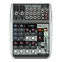
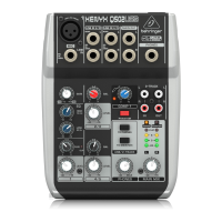
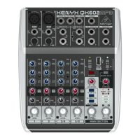
XENYX QX602MP3 Controls
(EN) Step 2: Controls
(1) MIC mono inputs o er a balanced microphone
input via the XLR connector and also features
switchable +48 V phantom power supply
for condenser microphones. To activate
phantom power, press the PHANTOM button.
When phantom power is active, the +48 V
LED directly above the VU METER level LEDs
will light up.
(2) LINE IN mono connections o er a balanced
line input using a ¼" TRS connector.
Unbalanced devices (mono jacks) can also be
connected to these inputs. Please remember
that you can only use either the microphone
or the line input of a channel at any one time.
You can never use both simultaneously!
(3) GAIN controls adjust the input level on mono
channels 1 and 2. This control should always
be turned fully counterclockwise whenever
you connect or disconnect a signal source
from the channel inputs.
(4) EQUALIZER knobs allow you to boost or cut
high, mid and low frequency ranges on each
mono input channels.
(5) AUX/FX knobs allow you to feed signals from
channels 1-6 and sum these signals to a mono
bus for external e ects or for the onboard
reverb and delay unit. For the internal reverb
and delay, the bus signal routes straight to the
processor, and the e ected signal can then
be blended back into the main mix by using
the FX RETURN knob. For external e ects,
the combined mono bus signal appears at
the console’s AUX SEND send output and
can be fed from there to an external e ects
device. The return from the e ects unit
is then brought back into the console on
the STEREO AUX RETURN connections and
blended back into the main mix by using the
AUX RETURN knob.
(6) PAN control determines the position of the
channel signal within the stereo image.
(7) CLIP LEDs on channels 1 and 2 light up
when the input signal exceeds the channels’
headroom, which can cause the signal
to distort. If the CLIP LED lights steadily,
reduce the input level by turning the GAIN
knobs counter-clockwise until the CLIP LED
only lights occasionally.
(8) BAL knobs adjust the relative left-right levels
of stereo signals routed into stereo channels
3/4 and 5/6 from the related LINE IN 3/4 and
LINE IN 5/6 inputs.
(9) LEVEL control determines the level of the
channel signal in the main mix.
(10) LINE IN 3/4 stereo inputs route stereo signals
into the 3/4 stereo channel. This input section
accepts balanced or unbalanced stereo signals
from devices using ¼" TRS connectors. To
connect mono signals, use the ¼" TRS jack
marked “MONO.”
(11) LINE IN 5/6 stereo inputs route stereo signals
into the 5/6 stereo channel. This input section
accepts balanced or unbalanced stereo signals
from devices using either ¼" TRS connectors
or ⁄" TRS connectors. To connect mono
signals, use the ¼" TRS jack marked “MONO.”
(12) STEREO AUX RETURN connectors let you
bring the output of an external e ects device
(fed by the signal from the AUX SEND jack)
back into the console. Use the AUX RETURN
knob to determine how much of the e ected
signal is sent to the main mix. You can also
use the STEREO AUX RETURN connections
as additional all-purpose signal inputs, but
any e ects returns will then need to route
back into the console via one the regular
input channels, either mono or stereo.
This alternate routing method does, however,
give you the ability to use channel EQ on
the e ects return signal if you wish. If the
return signal from the e ects unit is a mono
signal, use the STEREO AUX RETURN left
channel input.
(13) AUX SEND ¼" TRS output can be used to
send the combined mono signal from the
AUX/FX knobs out to an external e ects unit.
The e ected signal from the e ects unit is
then routed back into the mixer by using the
STEREO AUX RETURN inputs and blended into
the main mix by using the AUX RETURN knob
as a level control.
(14) PHONES lets you connect stereo headphones
that use a ¼" TRS plug. The headphone
output level is controlled by the PHONES/
CNTRL ROOM knob. The PHONES jack and
CNTRL ROOM OUT jacks share the same signal
and level control.
(15) CNTRL ROOM OUT ¼" TRS jacks send a
copy of the stereo main mix out to monitor
speakers or other devices. The CTRL ROOM
OUT level is controlled by the PHONES /
CTRL ROOM knob. The PHONES jack and CNTRL
ROOM OUT jacks share the same signal and
level control.
(16) MAIN OUT
¼" TRS jacks send the stereo main
mix out to monitor speakers, front-of-house
speakers or other devices. The MAIN OUT level
is controlled by the MAIN MIX knob.
(17) MP3 PLAYBACK input accepts USB
connections from USB ash drives with
MP3 les. The MP3 PLAYBACK controls
manage navigation and playback of the
ash drive’s MP3 les. To control the
routing of the MP3 playback inside the
mixer, press the TO LINE 5/6, TO PHNS/CTRL
or TO MAIN MIX buttons. The MP3 player
determines the track playing order based on
each audio le's date.
(18) PHANTOM button, when pressed,
sends +48 V of phantom power to the
XLR MIC inputs. When phantom power is
active, the +48 V LED directly above the
VU METER level indicator LEDs will light up.
(19) REVERB/DELAY button, when pressed,
selects the internal delay e ects processor.
When released, the button selects the internal
reverb e ects processor. To send signal to
the internal e ects processor from the input
channels, use the AUX/FX knobs.
(20) AUX RETURN knob controls the main mix
level of signals coming in through the STEREO
AUX RETURN jacks.
(21) FX RETURN knob controls the internal e ects
processor’s output level in the main mix.
(22) POWER LED lights up when the mixer has
been powered on.
(23) +48 V button lights up when the
PHANTOM button is pressed and phantom
power is active.
(24) MP3/TO LINE 5/6 button, when pressed,
sends the MP3 playback signal to stereo
channel 5/6. Sending MP3 playback to
channel 5/6 allows you to set the MP3 audio
level in the main mix by using channel
5/6’s LEVEL control.
(25) VU METER 4-segment level indicator LEDs
display the overall main mix signal level.
(26) MP3/TO PHNS/CTRL button, when pressed,
sends the MP3 playback signal to the PHONES
and CTRL ROOM OUT jacks.
(27) MP3/TO MAIN MIX button, when pressed,
sends the MP3 playback signal directly into
the main mix.
(28) MAIN MIX knob controls the nal output level
of the main mix at the MAIN OUT outputs.
(29) PHONES/CTRL ROOM knob controls the
output level of the main mix at the PHONES
and CNTRL ROOM OUT connections.
(30) AC INPUT jack is where you connect the
included power cable.
(31) POWER button switches the unit on and o .
 Loading...