Installation
4.
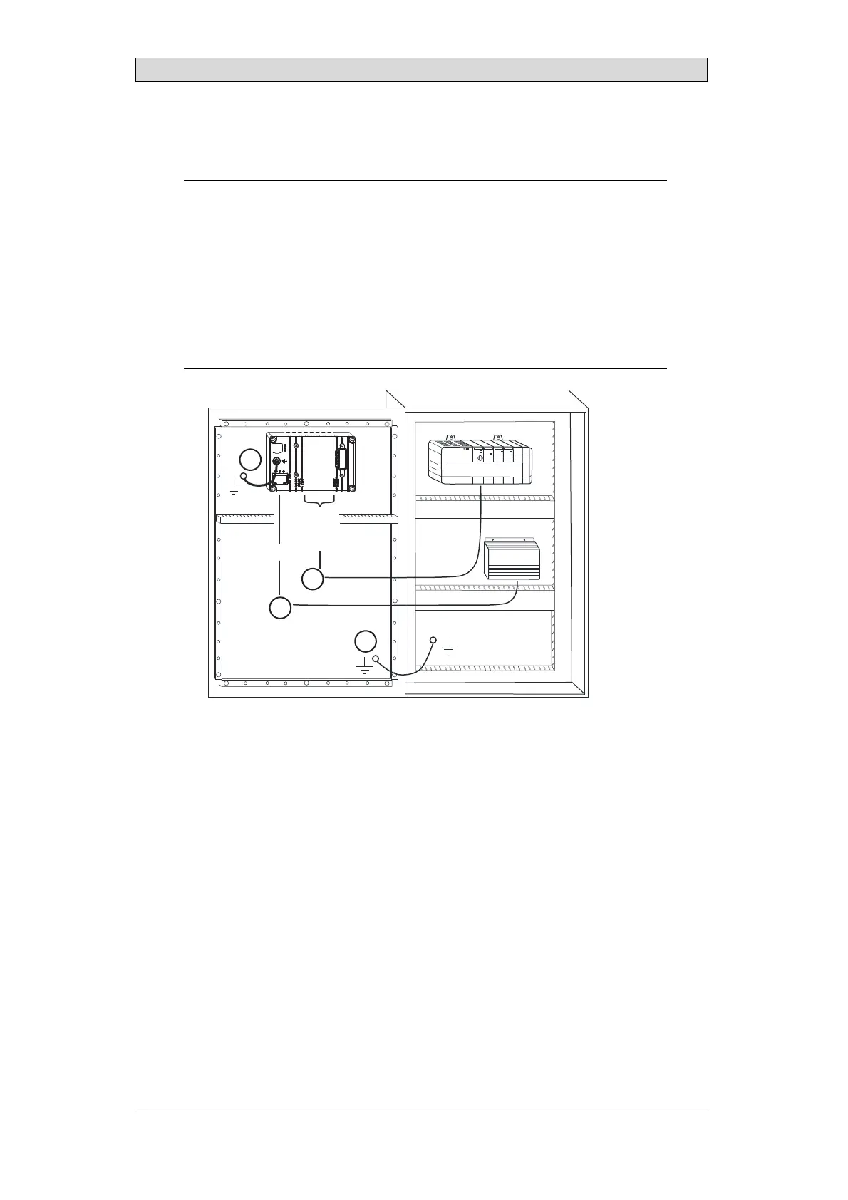
Connect the cables in the specified order, according to the drawing and steps
below.
Caution:
• The operator panel must be brought to ambienttemperature before itis started
up. If condensation forms, ensure that the operator panel is dry before connecting
it to the power o utlet.
• Ensurethat the operator panel and the controllersystem have the same electrical
grounding(reference voltage level), otherwise errors in communication may
occur.
• Ensure that the voltage and polarity of the power source is correct.
• Separatehigh voltage cablesfrom signal and supply cables.
• Shielded communication cables are recommended.
24V DC
RS422/
RS485
RS232
24V DC
A
D
Controller
Power
C
B
– Connect cable A.
– Connect cable B, using an M5 screw and a grounding conductor (as short
as possible), that is sized correctly according to local electrical codes.
– Connect cable C.
– Connect cable D.
5.
Carefully remove the laminated film over the operator panel display, to avoid
static electricity that could damage the panel.
Beijer Electronics, MAEN852B
9