Do you have a question about the BEKA BA574C and is the answer not in the manual?
Details the functions of the four push-buttons used for programming and operation.
Discusses enclosure types (GRP, aluminium) and suitability for different environments.
Summarizes the programmable parameters and their functions based on input type.
Conditions the transmitter for thermocouple, RTD, or voltage input.
Configures settings specific to thermocouple sensor inputs.
Configures settings specific to resistance thermometer sensor inputs.
Positions or turns off the dummy decimal point on the display.
Defines the lower voltage input and its corresponding transmitter display.
Defines the higher voltage input and its corresponding transmitter display.
Explains how to define the relationship between transmitter display and 4/20mA output.
Describes setting a four-digit code to protect access to menus and functions.
Explains how to calibrate the instrument's internal references for accurate readings.
Accesses the protected sub-menu for internal reference calibration.
Calibrates the internal reference for voltage inputs.
Calibrates the internal reference for 3-wire RTD inputs.
Calibrates the internal reference for 4-wire RTD inputs.
Calibrates the internal reference for the 4/20mA output current.
Details the procedure for adjusting the transmitter using an external calibrator.
Recommends annual checks and adjustments using the Trim Menu for ongoing accuracy.
Lists symptoms, causes, and solutions for common commissioning faults.
Provides guidance for troubleshooting issues that arise after the instrument is operational.
Explains that servicing involves exchanging electronic assemblies, not on-site repair.
Outlines the procedure for returning transmitters for repair under guarantee.
Invites customer feedback and suggestions for product improvement.
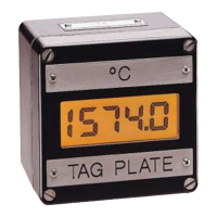
Describes options for custom engraving of scale and tag plates.
Details available kits for mounting the transmitter onto pipes.
Describes the kit for mounting the transmitter into a panel aperture.
Summarizes the programmable functions for alarms like enable, setpoint, and hysteresis.
Provides detailed descriptions of each programmable alarm function.
Enables or disables the alarm function without changing parameters.
Adjusts the alarm setpoints, which can be positioned anywhere in the display range.
Conditions an alarm to function as either a high or low alarm.
Determines if the alarm output is open or closed in the alarm condition.
Adjusts the hysteresis for alarms, affecting the reset point.
Sets a delay for alarm activation after the condition occurs.
Defines the time the alarm output remains silenced after acceptance.
Controls direct access to alarm setpoints from the display mode.
Allows adjustment of alarm setpoints directly from the display mode using a security code.
| Type | Transmitter |
|---|---|
| Model | BA574C |
| Manufacturer | BEKA |
| Display | LCD |
| Output | 4-20 mA |
| Hazardous Area Certification | ATEX, IECEx |
| IP Rating | IP66 |
| Input | 4-20mA |
| Accuracy | ±0.1% |
| Protection | Reverse polarity |