Do you have a question about the Beko HLV-550 and is the answer not in the manual?
Details on frequency range, gain, power limit, and performance metrics like spectral purity and IMD.
Covers high frequency energy, mains connection, user qualifications, operating environment, and duty cycle limits.
Specifies permitted mains voltages (180-260V AC) and frequencies (50-60 Hz) for operation.
Details on using N-type connectors, PTFE insulation, and proper cable handling to prevent damage.
Outlines the 2-year warranty, conditions that invalidate it, and specific damages excluded.
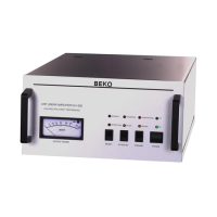
Explains how to turn on the amplifier, the 'ON'-LED, and the power-on sequence.
Describes activating external preamplifiers via the 'PREAMP' switch and its voltage supply.
Details the 'STANDBY' function, its effect on the RF unit, and associated indicator LEDs.
Explains how protection circuits activate (LEDs, sound), their triggers, and how to reset the unit.
Details triggers like reflected power, overdrive, and overheating (>55°C) that shut down the RF unit.
Explains how PTT or ground on the 'CONTROL' jack activates RX/TX switching.
Describes the internal sequencer, PTT function, and voltage supply for MOSFETs.
Advises on input power limits for SSB to maintain spectral purity and avoid distortion.
Details remote control of functions (RESET, PREAMP, PTT) via an external switch wired to ground.
Explains output power monitoring via 10V DC on Pin 5 of the 7-pin DIN plug.
Describes temperature-controlled axial blowers and increased airflow during TX operation.
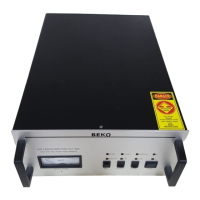
Warns against covering inlets/outlets and specifies duty cycle limits for safe operation.
Illustrates the main blocks: power supply, RF amplifier, couplers, and control board.
Guides on adjusting trimpots for protection circuits, emphasizing careful clockwise/counter-clockwise adjustments.