EasyManua.ls Logo

belavi PERGOLA User Manual

belavi PERGOLA
25 pages
To Next Page IconTo Next Page
Page #1 background imageLoading...
Page #1 background image
User Manual
________________
Manual
del usuario
PERGOLA
English.... Page 3
Español.... Página 25
PÉRGOLA
For Reference Only
Question and Answer IconNeed help?

Do you have a question about the belavi PERGOLA and is the answer not in the manual?

belavi PERGOLA Specifications

General IconGeneral
BrandBelavi
Water ResistanceYes
UV ProtectionYes
Assembly RequiredYes
MaterialSteel

Summary

Safety and Contents

Warnings & Cautions

Essential safety guidelines and precautions for assembly and use.

Pack Contents Overview

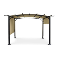
List of all parts included in the packaging for the pergola.

Assembly Instructions (Page 5)

Step 1: Crossbeam Assembly

Connect Crossbeams (B1, B2) using Connector (H) and Crossbeam Connector (N).

Step 2: Crossbeam and Plate Connection

Connect Crossbeams (C, D) using Plate (L) and bolts (AA, BB).

Assembly Instructions (Page 6)

Step 3: Canopy Support Assembly

Connect Canopy Supports (E1, E2) using Connector (H) and Crossbeam Connector (N).

Step 4: Pole and Foot Attachment

Attach Covers (K) and Feet (J) to Poles (A1, A2) using bolts (BB).

Assembly Instructions (Page 7)

Step 5: Pole and Crossbeam Integration

Connect assembled Crossbeams (B1, B2) to standing Poles (A1, A2) using bolts (DD, BB).

Assembly Instructions (Page 8)

Step 6: Final Crossbeam and Support Connection

Connect Crossbeams (C, D) to Poles (A1, A2) and attach Supports (I).

Assembly Instructions (Page 9)

Step 7: Canopy Support Installation

Place Canopy Supports (E1, E2) onto Crossbeams (C, D) and secure with bolts (DD).

Step 8: Canopy and Weight Bar Attachment

Place Canopy (Q) onto supports and insert Canopy Weight Bars (G1, G2).

Assembly Instructions (Page 10)

Step 9: Canopy Weight Bar Securing

Insert Slide Bars (M) through latches of Canopy Weight Bars (G1, G2).

Step 10: Slide Bar and Connector Installation

Connect Slide Bars (M) to Poles (A1, A2) via Slider Bar Connectors (F).

Final Assembly and Warranty (Page 11)

Step 11: Canopy Locking and Stability Stakes

Lock Canopy (Q) using latches and secure with Stakes (O) for stability.

Warranty Card Information

Details for filling out and using the warranty card for support.

Full Warranty Conditions

After Sales Support and Product Details

Related product manuals