800-543-9038 USA 866-805-7089 CANADA 203-791-8396 LATIN AMERICA / CARIBBEAN
AFB24-SR
AFB24-SR-S
AFX24-SR
AFX24-SR-S
roportional, Spring Return, 24 V, for 2 to 10 VDC to 4 to 20 mA Control Signal
Accessories
-2
h
ft
xt
n
i
-
Dam
er
osition indicator
KH-AF
Crank arm
K7-
Universal clamp
or up to 1.05” dia
acksha
ts
F-CC US Conduit fittin
-
mm
n
1
mm wr
n
ZG-10
Universal mounting bracke
ZG-10
Universal mounting bracke
Z
-118 Mountin
bracket for Barber
olman
MA 3..
4.., Hone
wel
Mod III or IV or Johnso
®
Series 100 re
lacement or new crank
arm t
e installation
Z
-AFB
rank arm adaptor kit
ZG-AFB118 Crank arm adaptor kit
Z
-100
eat
er s
e
meta
ZS-15
Weather shield (polycarbonate
Z
-26
xplosion-proof housin
ZS-30
EMA 4X housin
OTE
When usin
AFB24-SR, AFB24-SR-S, AFX24-SR and AFX24-SR-S actuators, only use
ccessor
es
ste
on t
s pa
e.
For actuator wirin
information and dia
rams, refer to Belimo Wirin
Guide
Typical Specification
Spring return control damper actuators shall be direct coupled type which require no
rank arm and linkage and be capable o
direct mounting to a jacksha
t up to a 1.05”
ameter.
e actuator must prov
e proport
ona
amper contro
n response to a 2 to
10 VDC or, with the addition of a 50
resistor, a 4 to 20 mA control input
rom an
ectron
c contro
er or pos
t
oner.
e actuators must
e
es
ne
so t
at t
ey may
e
sed
or either clockwise or counterclockwise
ail-sa
e operation. Actuators shall use
a brushless DC motor controlled by a microprocessor and be protected from overload
at all an
les o
rotation. Run time shall be constant, and independent o
torque. A 2 to
10 VDC feedback si
nal shall be provided for position feedback. Actuators shall be
ULus Approved and have a 5 year warranty, and be manufactured under I
9001
nternational Quality Control Standards. Actuators shall be as manufactured by Belimo.
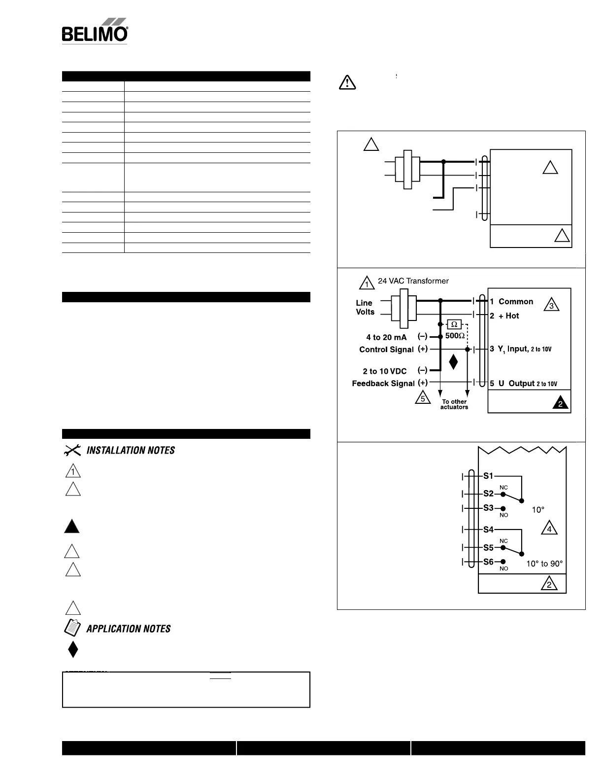
Wiring Diagrams
rovide overload
rotection and disconnect as re
uired
AUTI
N
qu
pment
ama
e
Actuators ma
be connected in
arallel.
ower consum
tion and in
ut im
edance must be observed.
2
U
to 4 actuators ma
be connected in
arallel if not mechanicall
mounted
t
th
m
h
ft. With 4
t
t
r
wir
t
n
r
i
t
r.
ower consum
tion must be observed
Actuator may also be powered by 24 VD
or end position indication, interlock control, fan startup, etc., AFB24-SR-S
and AFX24-
R-
incorporates two built-in auxiliary switches: 2 x
PDT, 3A
0.5A)
250 VA
, UL Approved, one switch is fi xed at +10°, one is adjust
able 10° to 90°
nly connect common to ne
.
–
le
of control circuits
he Z
-R01 500
res
stor converts t
e 4 to 20 m
contro
s
gna
t
2 t
1
VD
.
-
-
an
-
-
nn
n
m m
n
n
he same damper or valve shaft.
nly
n
ff and MFT AF models can be used for
an
em mount app
cat
ons.
Live Electrical Components!
During installation, testing, servicing and troubleshooting of this product, it may be
necessar
to work with live electrical com
onents. Have a
ualifi ed licensed electrician or other
individual who has been properly trained in handling live electrical components per
orm these
tasks. Failure to
ollow all electrical sa
ety precautions when exposed to live electrical compo
nents could result in death or serious injury
Control Signal
(+)
2 to 10 VDC
(–)
1 Common
2 + Hot
3 Y
1
Input,
2 to 10V
5 U Output 2 to 10V
1
2
3
24 VAC Transformer
AFB24-SR, AFB24-SR-S
AFX24-SR, AFX24-SR-S
Line
Volts
W068_AFB
X
24-SR
t
10 VD
c
ntr
l
AFB24-
R and AFX24-
R
AFB24-SR, AFB24-SR-S
AFX24-SR, AFX24-SR-S
W069_AFB
X
24-SR
to 20 mA control o
AFB24-
R and AFX24-
R with
to 10 VDC feedback out
u
AFB24-SR-S
AFX24-SR-S
W064_AFB
X
24_SR_-
Auxiliar
switches
or AFB24-
R-
, AFX24-
R-
AFB24 SR( S) d AFX24 SR( S)
N40103 - 09/11 - Subject to change. © Belimo Aircontrols (USA), Inc.
 Loading...


