Do you have a question about the Belimo AF24 US and is the answer not in the manual?
Overview of AF Series actuators, covering key specifications like torque, power, and control signals.
Step-by-step visual guide for quick and easy mechanical mounting of actuators.
Guidelines for calculating damper torque and selecting the appropriate actuator size.
Explanation of the direct coupling mechanism and spring return operation of AF series actuators.
Procedures for standard mounting, including clamp adjustment and anti-rotation strap attachment.
Specific steps for installing actuators on shafts that do not extend sufficiently from the duct.
Instructions for mounting actuators on jackshafts, including multiple actuator setups.
Guidance on using brackets for mounting multiple actuators on a single shaft for increased torque.
How to use the ZDB-AF2 US limiter to set maximum damper rotation angles.
Procedure for setting specific damper rotation limits using the angle of rotation limiter.
Steps to set a minimum damper position using manual override or control signals.
How to manually position the actuator for installation or emergency use.
Information on adjusting the built-in auxiliary switches for signaling or safety interlocks.
Techniques for mounting actuators when direct coupling to the shaft is not possible.
Details on using KH-AF crankarms for non-direct coupling applications.
Explanation of brushless DC motor technology and its benefits in AF actuators.
How AF actuators achieve precise control and stability, including deadband behavior.
Best practices for wiring AF actuators, including wire types, connections, and safety precautions.
Recommended maximum wire lengths for power supply connections to AF actuators based on gauge.
Guidelines for selecting and connecting transformers for powering AF actuators and controllers.
Step-by-step process for checking electrical connections and actuator response during startup.
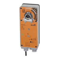
The AF Series Spring Return Direct Coupled Actuator is designed for the precise control of air dampers and valves in HVAC systems. These actuators provide a reliable fail-safe operation, ensuring positive close-off on airtight dampers. The spring return system maintains consistent torque to the damper, whether power is applied or not.
The AF Series actuators are available in various configurations, including On/Off, proportional, and multi-function (MFT) models, catering to a wide range of control requirements.
The AF Series actuators are designed for ease of installation and flexible application.
The AF Series actuators are designed for minimal maintenance and long service life.
| Housing Material | Polycarbonate |
|---|---|
| Auxiliary Switch | Optional |
| Protection Class | IP54 |
| Power Supply | 24 VAC 50/60 Hz |
| Control Type | On/Off |
| Input Signal | 0-10 V DC, 4-20 mA |
| Temperature Range | -20°C to +60°C (-4°F to +140°F) |
| Mounting Type | Direct mount |
| Running Time | 150 s |
| Overload Protection | Yes |
| Storage Temperature Range | -40…176°F [-40…80°C] |
| Humidity | 5% to 95% RH, non-condensing |
| Agency Listings | CE, UL |
| Rotation | 90° |
| Operating Temperature | -20°C to +60°C (-4°F to +140°F) |