EasyManua.ls Logo

Belimo AF120 US - User Manual

Belimo AF120 US
11 pages
Print Icon
To Next Page IconTo Next Page
Loading...
J20741 - Subject to change. © Belimo Aircontrols (USA), Inc.
Torque min. 133 in-lb, for control of air dampers
Application
For on-off, fail-safe control of dampers in HVAC systems.
Actuator sizing should be done in accordance with the damper
manufacturers specifications. Control is on-off from an auxil-
iary contact, or a manual switch.
The actuator is mounted directly to a damper shaft up to 1.05
in diameter by means of its universal clamp. A crankarm and
several mounting brackets are available for applications where
the actuator cannot be direct coupled to the damper shaft.
Operation
The AF series actuators provide true spring return operation for
reliable fail-safe application and positive close off on air tight
dampers. The spring return system provides consistent torque
to the damper with, and without, power applied to the actuator.
The AF series provide 95° of rotation and are provided with a
graduated position indicator showing 0° to 95°. The AF has a
unique manual positioning mechanism which allows the set-
ting of any damper position within its 95° of rotation. The AF
series actuators are shipped at +5° (5° from full fail-safe) to
provide automatic compression against damper gaskets for
tight shut-off. When power is applied to the AF series, the
manual mechanism is released. The actuators will now try to
close against the 0° position during its normal control opera-
tions. The manual override can also be released physically by
the use of a crank supplied with the actuator.
The AF uses a brushless DC motor which is controlled by an
Application Specific Integrated Circuit (ASIC). The ASIC monitors
and controls the actuators rotation and provides a digital rotation
sensing function to prevent damage to the actuator in a stall con-
dition. The actuator may be stalled anywhere in its normal rota-
tion without the need of mechanical end switches. The actuators
are Double Insulated so a ground connection is not required.
The AF120/230-S
US version is provided with 2 built-in auxil-
iary switches. These SPDT switches are provided for safety
interfacing or signaling, for example, for fan start-up. The
switching function at the fail-safe position is fixed at +5°, the
other switch function is adjustable between +25° to +85°.
Dimensions
[All numbers in brackets are in millimeters.]
AF120 (-S) US, AF230 (-S) US
On-off, Spring Return Fail-Safe, 120 or 230 VAC
1.97"
3.15" [80]
3.86" [98]
3.25" [82.7]
2.24"
[57]
[50]
1.93"
[49]
2.64"
[67]
0.26" [6.5]
5.85" [148.5]
10.47" [266]
0.35" [9]
0.39" [10]
0.65" [16.5]
0.19" [5]
K4-2 US (supplied)
1/2" Centered
(Default)
3/4" Centered
(Field Selectable)
1.05" Centered
(Field Selectable)
K4-1 US (optional)
3/4" to 1.05"
Adjustable
K4 US (optional)
3/8" to 3/4"
Adjustable
LISTED
94D5
TEMP. IND &
REG. EQUIP.
U
L
®
Technical Data AF120 (-S) US AF230 (-S) US
Power supply 120 VAC ± 10% 230 VAC ±14%
50/60 Hz 50/60 Hz
Power consumption running: 6 W 6.5 W
holding: 2.3 W 2.5 W
Transformer sizing 10 VA 11 VA
Electrical connection 3 ft, 18 GA appliance cable
1/2 conduit connector
Electrical protection actuators are double insulated
Overload protection electronic throughout 0° to 95° rotation
Angle of rotation 95°, adjustable 35 to 95° w/ ZDB-AF2
Torque 133 in-lb [15 Nm] constant
Direction of rotation reversible with CW/CCW mounting
Position indication visual indicator, 0° to 95° (0° is
spring return position)
Manual override 3mm hex crank (shipped w/actuator)
Auxiliary switches 2 x SPDT 7A (2.5A) @ 250 VAC,
UL listed
(AF120/230-S) one set at +5°, one adjustable 25° to 85°
Running time 150 sec. constant, independent of
load, spring return < 20 sec
Humidity 5 to 95% RH non-condensing
Ambient temperature -22°F to +122°F [-30°C to +50°C]
Storage temperature -40°F to +176°F [-40°C to +80°C]
Housing NEMA type 2 / IP54
Housing material zinc coated steel
Agency listings UL 873 listed, CSA C22.2 No. 24 certified
Noise level max. 45 dB (A)
Servicing maintenance free
Quality standard ISO 9001
Weight 6.9 lbs (3.1 kg)
22
D001
©
Question and Answer IconNeed help?

Do you have a question about the Belimo AF120 US and is the answer not in the manual?

Summary

Application

Application

On-off, fail-safe control of dampers in HVAC systems.

Operation

Describes spring return, manual positioning, and brushless DC motor functionality.

Dimensions

AF120 US, AF230 US Typical Specification

Wiring Diagrams

Quick-Mount Visual Instructions for Mechanical Installation

Determining Torque Loading and Actuator Sizing

Mechanical Operation

Standard Mounting

Short Shaft Installation

Jackshaft Installation

Multiple Actuator Mounting

Rotation Limitation

Mechanical Minimum Damper Position

Manual Override

Auxiliary Switches

Non-direct Mounting Methods

Electrical Operation

General

Overview of AF series electrical operation, ASIC, and brushless DC motors.

Brushless DC Motor Operation

How the brushless DC motor functions without brushes or commutators.

Overload Protection

How the actuator protects against overload and stall conditions.

Motor Position Detection

Explains Hall Effect sensors for precise motor positioning.

Control Accuracy and Stability

General Wiring Instructions

Transformer(s)

Requirements for transformers powering AF24 actuators, including VA rating and class 2.

Multiple Actuators, One Transformer

Rules for powering multiple actuators from a single transformer.

Multiple Actuators, Multiple Transformers

Guidelines for powering multiple actuators using separate transformers.

Wire Length for AF... Actuators

Specifies maximum wire lengths based on gauge for AF actuators.

Wire Type and Wire Installation Tips

Recommendations for wire types and installation practices, including shielding.

Initialization of the AF24-SR US, and AF24-MFT US

Describes the actuator's initialization process upon power application.

Electrical Check-out Procedure

Overview

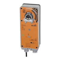
The Belimo AF120 (-S) US and AF230 (-S) US are on-off, spring return, fail-safe actuators designed for controlling air dampers in HVAC systems. These devices are engineered for reliable operation, providing positive close-off on airtight dampers and ensuring fail-safe functionality through their spring return mechanism.

Function Description

The primary function of these actuators is to provide on-off control for dampers. This control can be initiated by an auxiliary contact or a manual switch. The actuators are designed to mount directly to a damper shaft, accommodating diameters up to 1.05 inches using a universal clamp. For applications where direct coupling to the damper shaft is not feasible, a crankarm and various mounting brackets are available.

The AF series actuators utilize a brushless DC motor, which is controlled by an Application Specific Integrated Circuit (ASIC). This ASIC continuously monitors and controls the actuator's rotation, incorporating a digital rotation sensing function to prevent damage in stall conditions. This means the actuator can be stalled at any point in its rotation without requiring mechanical end switches, enhancing its durability and operational flexibility. The brushless DC motor technology also eliminates the need for brushes and commutators, which are common wear items in traditional DC motors, contributing to a maintenance-free design.

For overload protection, the ASIC constantly monitors the DC motor's rotation and stops pulses to the motor if a stall condition is detected. This allows the motor to remain energized and produce full rated torque, ensuring that dampers are fully closed and that blade seals are properly compressed.

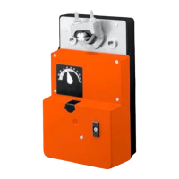
The AF series actuators provide 95° of rotation and feature a graduated position indicator, displaying positions from 0° to 95°. The 0° position represents the spring return position. A unique manual positioning mechanism allows users to set the damper at any desired position within its 95° range. The actuators are shipped with a +5° preload (5° from full fail-safe) to automatically compress damper gaskets for tight shut-off. When power is applied, the manual mechanism is released, and the actuator attempts to close to the 0° position during normal control operations. The manual override can also be physically released using a supplied crank.

The AF120/230-S US versions include two built-in auxiliary switches (SPDT). These switches are useful for safety interfacing or signaling, such as fan start-up. One switch's function at the fail-safe position is fixed at +5°, while the other switch's function is adjustable between +25° and +85°.

Usage Features

  • Direct Damper Shaft Mounting: The actuators can be directly mounted to damper shafts up to 1.05 inches in diameter using a universal clamp, simplifying installation.
  • Flexible Mounting Options: For non-direct coupling scenarios, crankarms and various mounting brackets (e.g., ZG-100, ZG-101, ZG-102, ZG-106, ZG-107, ZG-108) are available, offering versatility for different application requirements.
  • Reversible Rotation: The actuators support reversible rotation with both CW (clockwise) and CCW (counterclockwise) mounting, allowing for flexible installation depending on the desired fail-safe direction.
  • Manual Override: A manual override mechanism, accessible via a 3mm hex crank (supplied with the actuator), allows for manual positioning of the damper. This is particularly useful during installation, for emergency positioning, or for testing without power. The manual override can be locked into position and then released either by rotating the crank a quarter turn or by applying power to the unit for more than 3 seconds.
  • Position Indication: A visual indicator displays the actuator's position from 0° to 95°, with 0° being the spring return position, providing clear feedback on damper status.
  • Adjustable Angle of Rotation: The angle of rotation can be adjusted from 35° to 95° using the ZDB-AF2 accessory, allowing for fine-tuning to specific damper requirements.
  • Auxiliary Switches (AF120/230-S US): The inclusion of two SPDT auxiliary switches provides additional control and feedback capabilities. One switch is fixed at the fail-safe position (+5°), while the other is adjustable from +25° to +85°, enabling customized interlock control or signaling.
  • Short Shaft Installation: Specific instructions are provided for installing the actuator on short shafts (at least 3/4" from the duct), ensuring proper mounting in various duct configurations.
  • Multiple Actuator Mounting: If more torque is required than a single AF actuator can provide, a second AF actuator can be mounted to the shaft using the ZG-102 multiple mounting bracket. However, the manual positioning mechanism cannot be used in multiple actuator applications.
  • Rotation Limitation: The ZDB-AF2 angle of rotation limiter can be used to control the rotational output of the AF series actuator, particularly for dampers with designed rotations less than 90° or for setting a minimum damper position.

Maintenance Features

  • Maintenance-Free Design: The use of a brushless DC motor and an ASIC for control eliminates components prone to wear, such as brushes and commutators, contributing to a maintenance-free operational life.
  • Double Insulated: The actuators are double insulated, eliminating the need for a ground connection and simplifying electrical installation while enhancing safety.
  • Overload Protection: The integrated overload protection system prevents damage to the actuator in stall conditions, reducing the likelihood of failures and the need for repairs.
  • Robust Construction: The housing is made of zinc-coated steel, providing durability and protection against environmental factors. The NEMA type 2 / IP54 rating indicates protection against dust and splashing water.
  • Diagnostic Capabilities: The startup and checkout instructions include a detailed electrical check-out procedure to help identify and troubleshoot common issues, such as power wiring problems, incorrect control signals, or insufficient torque, facilitating quick and efficient problem resolution.
  • Warranty: A 5-year warranty underscores the manufacturer's confidence in the product's reliability and durability, offering peace of mind regarding long-term performance.

Belimo AF120 US Specifications

General IconGeneral
Power Supply24 VAC/DC
Control TypeModulating
Angle of Rotation90°
Mounting TypeDirect Mount
Protection ClassIP54
Housing MaterialPolyamide
Torque12 Nm
Power Consumption Holding1 W
Auxiliary SwitchSPDT
Temperature Range-30 to 50 °C

Related product manuals