This method should not be used for outside air damper appli-
cations. The damper will never go to the full close-off position.
This may cause coils to freeze or other system problems. The
AF24-SR (-S) US wired to either the SGA24 or SGF24 can be
used for minimum position setting and still provide full close-off.
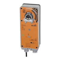
Manual Override
The AF series actuators can be manually positioned to ease
installation or for emergency positioning.
1. The manual override will only work if no power is available
to the actuator.
2. Insert the manual crank (shipped with the actuator) into
the hexagon hole located on either side of the actuator. An
illustration, located on the label, shows the location.
3. Turn the crank in the direction shown on the label (clock-
wise on the “CW” side, counterclockwise on the “CCW”
side). It will take approximately 19 revolutions to rotate
the full 95° of rotation.
4. To lock the actuator in the required position, rotate the
crank quickly in the opposite direction, 1/2 of a revolution. The
“lock closed” icon on the label shows the correct direction.
5. The manual override may be disengaged in 2 ways.
- Rotate the crank about a 1/4 revolution in the same
direction as the initial winding. The “lock open” icon
shows the correct direction.
- Apply power to wire 1 and 2. The actuator will automati-
cally disengage the override function and will go to the
“on” position in the case of the on-off versions. Or, in the
case of the proportional versions, go to the 0 signal posi-
tion and then go to the position corresponding to the
control signal. The actuator will now work normally.
Testing the installation Without Power
The actuator/damper installation may be tested without power
at the actuator. Refer to the manual positioning section of the
instructions. Move the damper to its full non-fail-safe position
using the manual crank. Disengage the manual position
mechanism and have the damper go to full fail-safe position.
Correct any mechanical problems and retest.
Auxiliary Switches
The AF series actuators may be ordered with 2 built-in SPDT
auxiliary switches used for safety interfacing or signalling, for
example, for fan start-up. The switch position near the fail-safe
position is fixed at 5°. The other is adjustable between 25 and
85° of rotation. The crank, supplied with the actuator, or a 3mm
allen wrench is used to adjust the switching position.
Switch Rating
Voltage Resistive Load Inductive Load
120 VAC 7A 5A
250 VAC 7A 2.5A
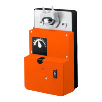
Two methods may be used to adjust the switching point of the
adjustable switch.
Method 1 - See Fig. F
1 The actuator must be in its fail-safe position.
2. Insert the crank into the hexagon shaped hole located in
the center of the adjustable switch pointer.
3. Rotate the crank until the switch pointer is at the desired
switch point in degrees as shown.
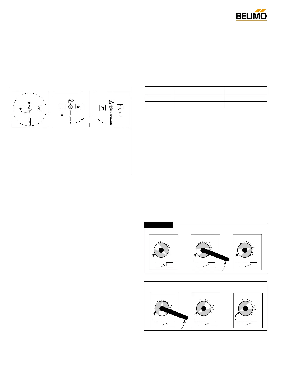
Method 2 - See Fig. G
1. Position the damper to the point at which you want the
switch to activate. This may be done by using the manual
override or by providing the appropriate proportional sig-
nal to AF24… modulating type actuator. The position of
the switch pointer is not important during this step.
2. Insert the crank into the hexagon shaped hole located in
the center of the adjustable switch pointer.
3. Rotate the switch pointer to just past the switch point indi-
cating arrow as shown.
 Loading...