38
J20741 - Subject to change. © Belimo Aircontrols (USA), Inc.
Installation Instructions
Mechanical Installation
adequate shaft length, slide the actuator over the shaft
with the side marked “CCW” (or the “CW” side if this is the
side with the clamp). If the shaft extends at least 1/8”
through the clamp, mount the actuator as follows. If not,
go to the Short Shaft Installation section.
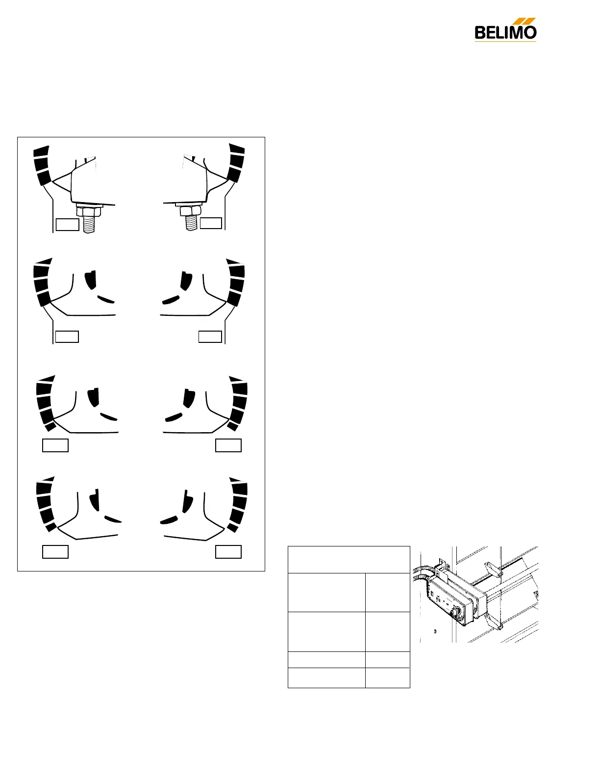
Fig. A Universal Clamp and IND-AF2 Pointer (optional)
positions indicating fail-safe and pre-load settings
3. If the clamp is not on the correct side as determined in step
#1, re-mount the clamp as follows. If it is on the correct
side, proceed to step #5. Look at the universal clamp. If
you are mounting the actuator with the “CCW” side out,
position the clamp so that the pointer section of the tab is
pointing to 0° (see Fig. C) and the spline pattern of the
clamp mates with spline of the actuator. Slip the clamp
over the spline. (Use the same procedure if the “CW” side is
out.) If your application requires a mechanical minimum
position, read the Rotation Limiting, Mechanical Minimum
Damper Position section.
4. Lock the clamp to the actuator using the retaining clip.
5. Verify that the damper is still in its full fail-safe position.
6. Slide the actuator over the shaft.
7. Position the actuator in the desired location.
8. Tighten the two nuts on the clamp using a 10mm wrench
or socket using 6-8 ft-lb of torque.
9. Slip the stud of the anti rotation strap into the slot at the
base of the actuator. The stud should be positioned
approximately 1/16 of an inch from the closed end of the
slot. Bend the strap as needed to reach the duct. Attach
the strap to the duct with #8 self tapping screws.
Short Shaft Installation
If the shaft extends at least 3/4” from the duct, follow these
steps:
1. Determine the best orientation for the universal clamp on
the back of the actuator. The best location would be where
you have the easiest access to the V bolt nuts on the
clamp.
2. Engage the clamp to the actuator as close as possible to
the determined location.
3. Lock the clamp in place using the remaining retainer clip.
4. Verify that the damper is still in its full fail-safe position.
5. Slide the actuator over the shaft.
6. Position the actuator in the desired location.
7. Tighten the two nuts on the clamp using a 10mm wrench
or socket using 6-8 ft-lb of torque.
8. Slip the stud of the anti-rotation strap into the slot at the
base of the actuator. The stud should be positioned
approximately 1/16 of an inch from the closed end of the
slot. Bend the strap as needed to reach the duct. Attach
the strap to the duct with #8 self tapping screws.
9. If damper position indication is required, use the optional
IND-AF2 pointer. See Fig. A.
Jackshaft Installation
The AF… series actuator is designed for use with jackshafts
up to 1.05” in diameter. In most applications, the AF actuator
may be mounted in the same manner as a standard damper
shaft application. If more torque is required than one AF actu-
ator can provide, a second AF actuator may be mounted to
the jackshaft using the ZG-102 multiple actuator mounting
bracket. See wiring guide for wiring details.
full fail-safe.
full fail-safe.
 Loading...