800-543-9038 USA 866-805-7089 CANADA 203-791-8396 LATIN AMERICA
31
AF24-MFT (-S) US
Proportional Damper Actuator, Spring Return Fail-Safe, Multi-Function Technology
®
Wiring Diagrams
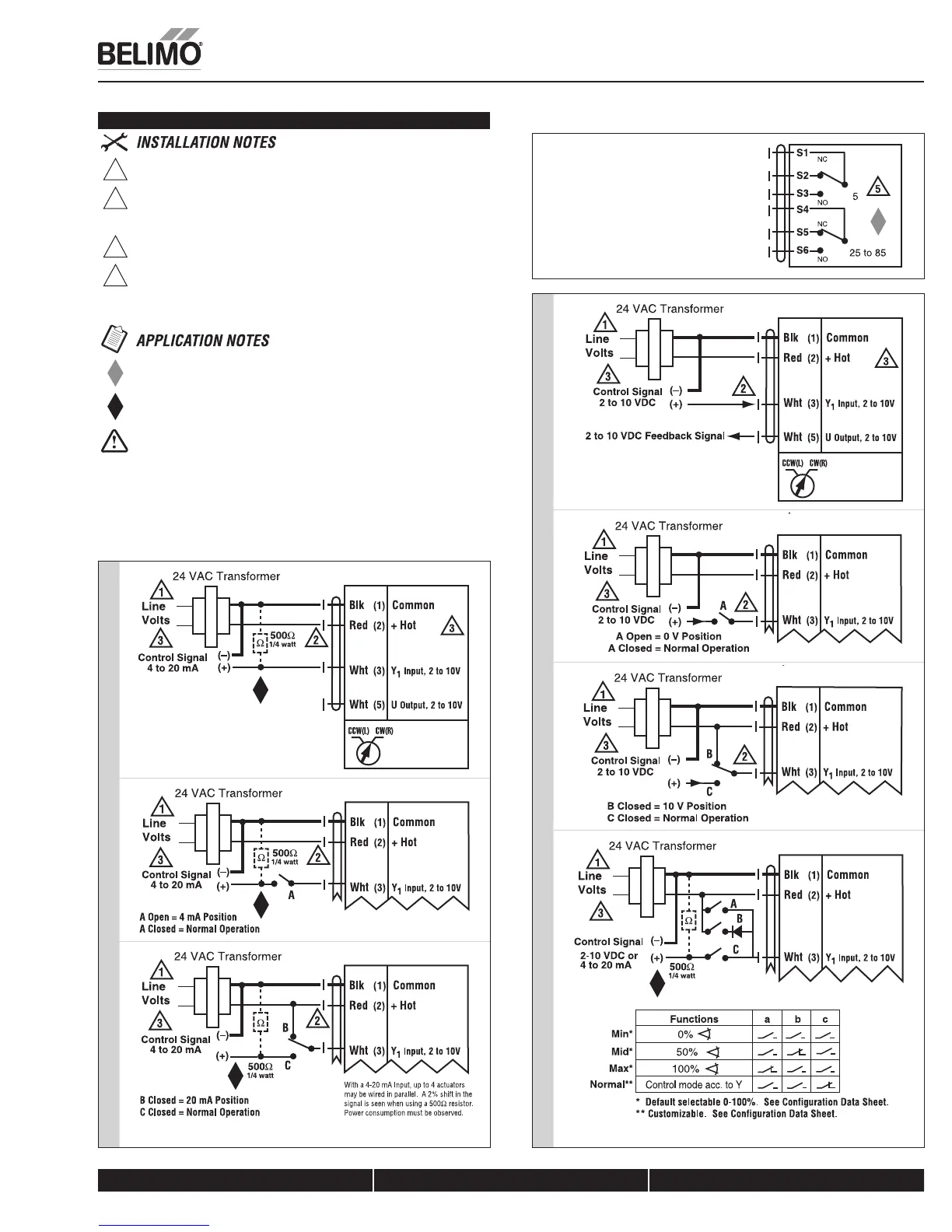
1
Provide overload protection and disconnect as required.
2
CAUTION Equipment damage!
Actuators may be connected in parallel if not mechanically mounted to the
same shaft. Power consumption and input impedance must be observed.
3
Actuators may also be powered by 24 VDC.
5
For end position indication, interlock control, fan startup, etc., AF24-MFT-
S US incorporates two built-in auxiliary switches: 2 x SPDT, 7A (2.5A)
@250 VAC, UL Approved, one switch is fixed at +5, one is adjustable 25
to 85.
Meets cULus requirements without the need of an electrical ground
connection.
The ZG-R01 500 7 resistor may be used.
WARNING Live Electrical Components!
During installation, testing, servicing and troubleshooting of this product, it maybe
necessary to work with live electrical components. Have a qualified licensed electrician
or other individual who has been properly trained in handling live electrical components
perform these tasks. Failure to follow all electrical safety precautions when exposed to live
electrical components could result in death or serious injury.
Auxiliary Switch AF24-MFT-S US
Standard Wiring
W012_08
Override to Zero PositionOverride to 10V PositionOverride control to min, mid, max, positions
2 to 10 VDC control signal
Standard Wiring
W013_08
Override to Zero PositionOverride to 20 mA Position
4 to 20 mA control signal
K20901 - 01/09 - Subject to change. © Belimo Aircontrols (USA), Inc.