800-543-9038 USA 866-805-7089 CANADA 203-791-8396 LATIN AMERICA / CARIBBEAN
7
• Tor
ue m
n. 180
n-l
•
ontrol
ixed
0 to 135
input, or Honeywell series 90
ixed
• Feedback 2 to 10 VD
(DEFAULT
A
licatio
For
ro
ortional modulation of dam
ers and control valves in HVAC s
stems. The
FB24-MFT95 N4(H), AFX24-MFT95 N4 provides mechanical spring return operation
for reliable fail-safe application.
Default/Confi
uratio
Default
arameters for 0 to 135
Input applications of the AFB24-MFT95 N4(H) and
FX24-MFT95 N4 actuator are assi
ned durin
manufacturin
. If required, custom
versions of the actuator can be ordered. However the control input cannot be modified
via MFT PC tool software. The
arameters noted in the Technical Data table are variable.
ese parameters can
e c
ange
y t
ree means
• Pre-set confi
urations from Belimo
• Custom confi
urations from Belimo
• Configurations set by the customer using the MFT PC tool (version 3.4 or higher)
software a
lication
O
eratio
The AFB24-MFT95 N4
H
, AFX24-MFT95 N4 actuator provides 95° o
rotation and is
rov
e
w
t
a
ra
uate
pos
t
on
n
cator s
ow
n
0° to 95°.
e actuator w
sync
ron
ze t
e 0° mec
an
ca
stop or t
e p
ys
ca
amper or va
ve mec
an
ca
stop
nd use this point
or its zero position during normal control operations. A unique
manual override allows the settin
o
any actuator position within its 95° o
rotation
with no
ower a
lied.This mechanism can be released
h
sicall
b
the use o
a
cran
supp
e
w
t
t
e actuator.
en power
s app
e
t
e manua
overr
e
s
eleased and the actuator drives toward the
ail-sa
e position.
The actuator uses a brushless DC motor which is controlled by an Application Specific
Integrated Circuit (ASIC) and a microprocessor. The microprocessor provides the
intelli
ence to the A
I
to provide a constant rotation rate and to know the actuator’s
exact position. The ASIC monitors and controls the brushless DC motor’s rotation and
rovides a Digital Rotation
ensing (DR
) function to prevent damage to the actuator
in a stall condition. The position
eedback si
nal is
enerated without the need
or
mechanical feedback potentiometers using DRS. The actuator may be stalled
n
where in its normal rotation without the need o
mechanical end switches.
The AFB24-MFT95 N4(H), AFX24-MFT95 N4 is mounted directly to control sha
ts up to
1.05” diameter b
means o
its universal clam
and anti-rotation bracket. A crank arm
nd several mounting brackets are available
or damper applications where the
ctuator cannot be direct coupled to the damper shaft. The sprin
return system
rovides minimum specified torque to the application durin
a power interruption.
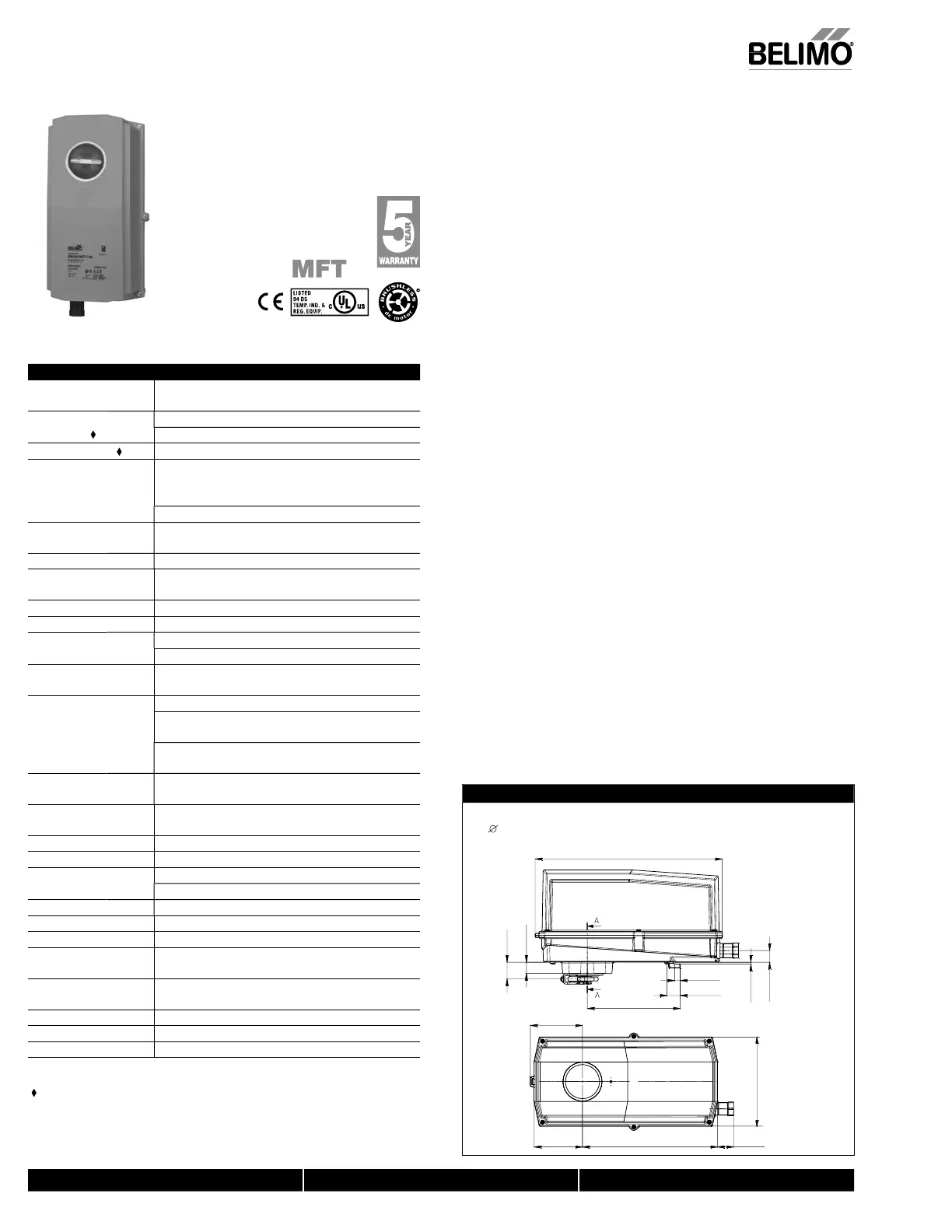
Dimensions (inches [mm])
6.77” [172]
Clamp Congurations
1/2” Field Selectable 3/4” Centered 1.05” Centered
(Default) (Field Selectable)
12.99” [330]
6.45” [163.9]
0.39” [10]
0.92” [23.4]
3.62” [92.1]
9.37” [238] 1.12” [28.5]
3.36” [85.2]
3.5” [0.14]
0.81” [20.5]
1.17” [29.8]
0.79” [20]
D312_confi
Technical Data AFB24-MFT95 N4(H), AFX24-MFT95 N4
Power su
l
24 VAC, +/- 20%, 50/60 H
24 VDC, +20% / -10%
P
w
r
consum
tio
runnin
7.
W
h
t
r 2
W
holdin
3 W
Trans
ormer sizin
10 VA
Class 2 power source
/ heater 25 V
ectr
ca
connect
o
AFB24-MFT95 N
3 ft, 18
A plenum cable
with 1/2” conduit connector
heater
N4H
terminal block
26-16 G
AFX24-MFT
N4 3 ft
1m
, 18 GA plenum cable
with 1
2”
n
it
nn
t
r
Overload
rotectio
electronic throu
hout 0 to 95° rotatio
Operatin
ran
e Y
t
Hone
well Electronic Series 90,
0 to 135
nput
Feedback output U
2 to 10 VDC, 0.5 mA ma
Torque
inimum 180 in-lb
20 Nm
Directio
o
rotation*
sprin
reversible with cw/ccw mountin
inside housin
mo
or reversible with built-in switch
echanical
an
le of rotation
95°
ad
ustable with mechanical end stop, 35° to 95°
Runnin
time
t
r* 150 seconds
default
, variable
70 to 220 seconds
spr
n
<20 seconds
-4°F to 122°F [-20°
to 50°
]
<60 seconds @ -22°F [-30°C
pr
ng
w
t
eater
<20 seconds
-4°F to 122°F [-20°
to 50°
]
<60 seconds
-49°F
-45°
An
le o
rotation
adaptation
o
de
ault
Position indicatio
visual indicator
0° to 95
0°
s spr
ng return pos
t
on
n
l
v
rri
5 mm hex crank
₁₆" Allen
, supplied
um
ty
ax. 95%
non-con
ens
n
m
ent temperatur
-22°F to 122° F
-30°C to 50°C
t
t
r -49°F to 122°F [-45°
to 50°
torage temperature -40°F to 176° F [-40°
to 80°
ous
n
e 4,
4,
66
Housin
material polycarbonate
N
i
l
v
0dB
A
motor @ 150 seconds, run time dependen
2
spr
n
return
ency
st
n
s † cULus acc. to UL60730-1A
-2-14
AN
A E60730
1:02
CE acc. to 2004/108/EC & 2006/95/EC
uality standard I
1
ervicing
aintenance
re
e
g
9.7
s.
4.4
g
; 10.5
s
4.8
g
w
t
eater
Variable when con
igured with MFT options
† Rated Impulse Volta
e 800V, Type of action 1.AA
1.AA.B for -
version
,
ontrol Pollution De
ree 4.
Programmed for 70 seconds motor run time. At 150 sec motor run time, transformer sizing is 8.5 V
nd power consumption is 6 W runnin
3 W holdin
AFB24-MFT95 N4(H), AFX24-MFT95 N4
EMA 4, Proportional, Sprin
Return, 24 V, for Use with Honeywell
®
Electronic Series 90 or a 0 to 135
n
u
N40103 - 09/11 - Subject to change. © Belimo Aircontrols (USA), Inc
 Loading...


