800-543-9038 USA 866-805-7089 CANADA 203-791-8396 LATIN AMERICA / CARIBBEAN
nstallation Instruction
Mechan
cal Installat
o
Determining Torque Loading and Actuator Sizing
amper torque loadin
s, used in selectin
the correct size actuator, should be
provided by the damper manu
acturer. I
this in
ormation is not available, the
ollowing general selection guidelines can be used
am
er T
Torque Loadin
Opposed blade, without edge seals
for non-ti
ht close-off applications
3 in-lb/sq. ft
Parallel blade, without ed
e seals
for non-ti
ht close-off applications
in-lb
sq. ft
Opposed blade, with edge seals
for tight close-off application
in-lb/sq. ft
Parallel blade, with edge seals
or tight close-o
application
7 in-lb/sq. ft
he above torque loadings will work for most applications with 1000 FPM face
velocity. For applications between this criteria and 2500 FPM, the torque loadin
should be increased by a multiplier of 1.5. If the application calls for hi
her criteria
up to 3000 FPM, use a multiplier o
2.0
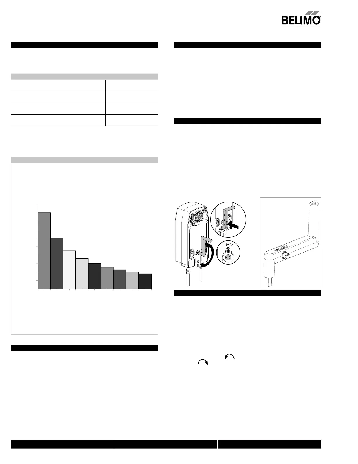
orque Loading Chart
Torque Loading Chart
0
10
20
30
40
50
60
70
80
90
100
2345678910
Torque Loading (in-lb/ sq. ft.)
Damper Area (sq. ft.)
General Information
elimo actuators should be mounted indoors in a dry, relatively clean environment
ree
rom corrosive
umes. I
the actuator is to be mounted outdoors, a protective
n
l
r
m
t
t
hi
l
th
t
t
r.
or new construct
on wor
,
rder dam
ers with extended sha
ts.
n
tr
t t
installing contractor to allow space
or mounting and service o
the Belimo actuator on
he shaft. The damper shaft must extend at least 3 1
2” from the duct. If the shaft
xtends less than 3-1/2” or if an obstruction blocks access, the shaft can be extended
with the AV 8-25 shaft extension accessor
or the actuator ma
be mounted in its short
shaft configuration.
Mechanical Operation
he actuator is mounted directl
to a dam
er sha
t u
to 1.05” in diameter b
means o
its universal clamp. A crank arm and several mounting brackets are
vailable for a
lications where the actuator cannot be direct cou
led to the dam
er
ha
t. The AFB, AFX series actuators provide true spring return operation
or reliable
ail-sa
e application and positive close-o
on air tight dampers. The spring return
stem
rovides constant tor
ue to the dam
er with, and without,
ower a
lied to
the actuator. The AFB…-S, AFX…-S versions are provided with two built-in
uxiliary switches. These SPDT switches are provided for safety interfacin
or
ignaling, for example, for fan start-up. The switching function at the fail-safe position
s fixed at +10°, the other switch function is ad
ustable between +10° to +90°.
Automatic Airtight Dampers/Manual Override
he AFB, AFX series provides 95° o
rotation and is provided with a graduated
osition indicator showin
0° to 95°.
e
,
as a un
que
u
t
n manua
pos
t
on
ng mec
an
sm w
c
a
ows t
e
etting of any damper position within its 95° of rotation. A pre-tensioned spring
utomatically ti
htens the damper when power is applied to the actuator,
compensatin
or damper seal deterioration.
he actuator is shipped at +5°
5° from full fail-safe
to provide automatic
compression a
ainst damper
askets
or ti
ht shut-o
. When power is applied, the
manual mechanism is released and the actuator drives toward the
ull
ail-sa
e
osition.
Standard Mounting
N
TE: The AFB, AFX…series actuator is shi
ed with the manual override
djusted
or a +5° position at the universal clamp
not at
ull
ail-sa
e, 0°
.
his allows for automatic com
ression of dam
er blade seals when the
ctuator is in use, providin
ti
ht shut-o
. This assumes that the damper is to
ave tight shut-off at the fail-safe position. If tight close-off is desired at the
osite direction
rom
ail-sa
e, the manual override should be released so
he actuator can
o to the
ull
ail-sa
e position.
ee the manual override
nstruct
ns
1. Manually move the damper to the
ail-sa
e position
usually closed
. I
the sha
t
rotated counterclockwise (
), this is a CCW installation. If the shaft rotated
), this is a CW installation. In a CCW installation, the actuator side
marked “CCW” faces out, while in a CW installation, the side marked “CW” faces
ut. All other ste
s are identical.
2. The actuator is usually shipped with the universal clamp mounted to the “
W”
ide of the actuator. To test for adequate shaft len
th, slide the actuator over the
haft with the side marked “CCW”
or the “CW” side if this is the side with the
clamp). If the shaft extends at least 1/8” through the clamp, mount the actuator
s follows. If not, go to the
. I
the clamp is not on the correct side as determined in step #1, re-mount the
clamp as
ollows. I
it is on the correct side, proceed to step #5. Look at the
niversal clamp. If you are mountin
the actuator with the “CCW” side out,
N40103 - 09/11 - Subject to change. © Belimo Aircontrols (USA), Inc
 Loading...


