800-543-9038 USA 866-805-7089 CANADA 203-791-8396 LATIN AMERICA / CARIBBEAN
4
nsta
at
on
nstruct
on
h
ni
l In
t
ll
ti
Manual Override
e
series actuators can be manually positioned to ease installation or for
emergency pos
t
on
ng.
. The manual override will only work i
no power is available to the actuator.
2. Insert the manual crank (shipped with the actuator) into the hexagon hole located
n either side o
the actuator. An illustration
located on the label
shows the
ti
n
3. Turn the crank in the direction shown on the label
clockwise on the “
W” side,
ounterclockwise on the “
W” side). It will take approximately 23 revolutions to
otate the full 95° of rotation
. To lock the actuator in the required position,
lip the switch to the locked position
that is located to the ri
ht of the crank on the CCW side of the actuator
left of
the crank on the CW side
.
. The manual override may be disengaged in 2 ways.
- Flip the switch to the unlocked position and the actuator will go to its fail-safe
position.
-
pp
y power to w
re 1 an
2.
e actuator w
automat
ca
y
sengage t
e
override function and will go to the “on” position in the case of the On/Off
versions. Or, in the case of the proportional versions,
o to the 0 si
nal
position and then
o to the position correspondin
to the control si
nal. The
actuator w
now wor
norma
.
CW Side Example:
W
nd
ng the
damper actuator
-
nsert cran
an
- t
rn
n
n
r
t
n
o
arro
Lock
ng the
amper actuator
-
p t
e
oc
sw
tc
to
t
e pos
t
on po
nt
n
to
t
e
oc
e
sym
o
Unlock
ng the
damper actuato
2 opt
ons
t
e
oc
sw
tc
to
e pos
t
on po
nt
n
to
e
un
oc
e
sym
o
.
emote contro
upp
y
ng power to t
e
nit
r > th
n
Testing the installation Without Power
he actuator
damper installation may be tested without power at the actuator. Refer
to the manual positioning section o
the instructions. Move the damper to its
ull
on-
ail-sa
e position using the manual crank. Disengage the manual position
echanism and have the damper go to full fail-safe position.
orrect any
echanical problems and retest
Auxiliary Switches
he AFB, AFX series actuators ma
be ordered with two built-in
PDT auxiliar
switches used
or sa
ety inter
acing or signaling,
or example,
or
an start-up. The
switch position near the
ail-sa
e position is
ixed at 10°. The other is adjustable
etween 10° and 90° o
rotation. The crank that is supplied with the actuator is used
to chan
e the switch position.
SWITCH RATING
Voltage Resistive Loa
nductive Loa
2
VA
1.
50 VA
0.5
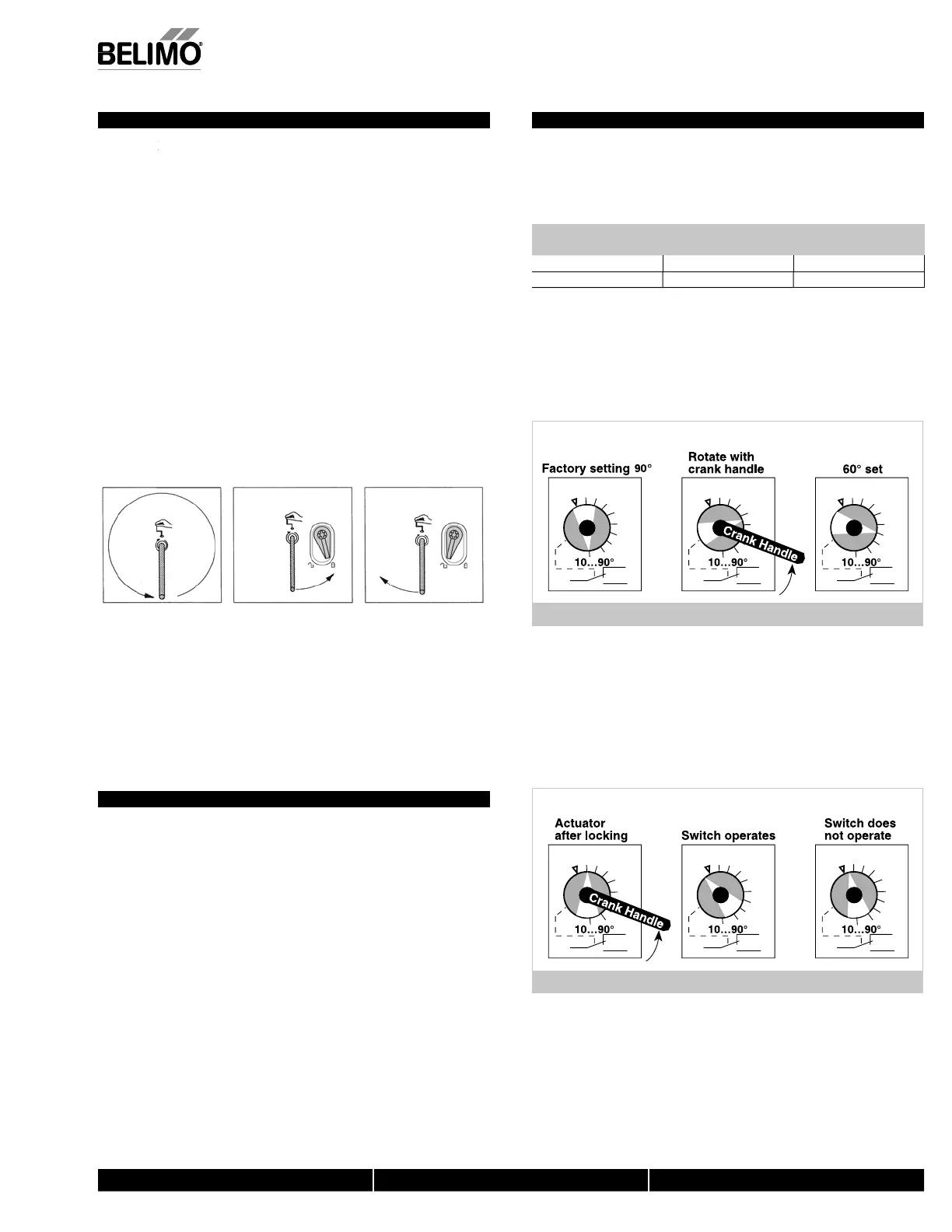
wo methods may be used to adjust the switching point of the adjustable switch
Meth
d 1 - See
i
ure
1 The actuator must be in its fail-safe position.
. Insert the crank handle into the torx shaped hole located in the center of the
a
usta
e sw
tc
po
nter
3.
ently rotate the crank until the switch pointer is at the desired switch point in
egrees as s
own.
,
...
erie
.2
.4
.6
.8
.2
.4
.6
.8
.2
.4
.6
.8
IGURE F
et
o
- See
igure
1. Position the damper to the point at which you want the switch to activate. This
may be done by usin
the manual override or by providin
the appropriate
proportional si
nal to AFB24, AFX24… modulatin
type actuator. The position of
the switch pointer is not important durin
this ste
. Insert the crank into the torx shaped hole located in the center o
the ad
ustable
w
tc
po
nter
3.
ently rotate the switch pointer to just past the switch point indicating arrow as
hown.
AFB, AF
...
ri
.2
.4
.6
.8
.2
.4
.6
.8
.2
.4
.6
.8
I
RE
N40103 - 09
11 -
ub
ect to chan
e.
Belimo Aircontrols
U
A
, Inc.
 Loading...


