Wiring Diagrams
INSTALLATION NOTES
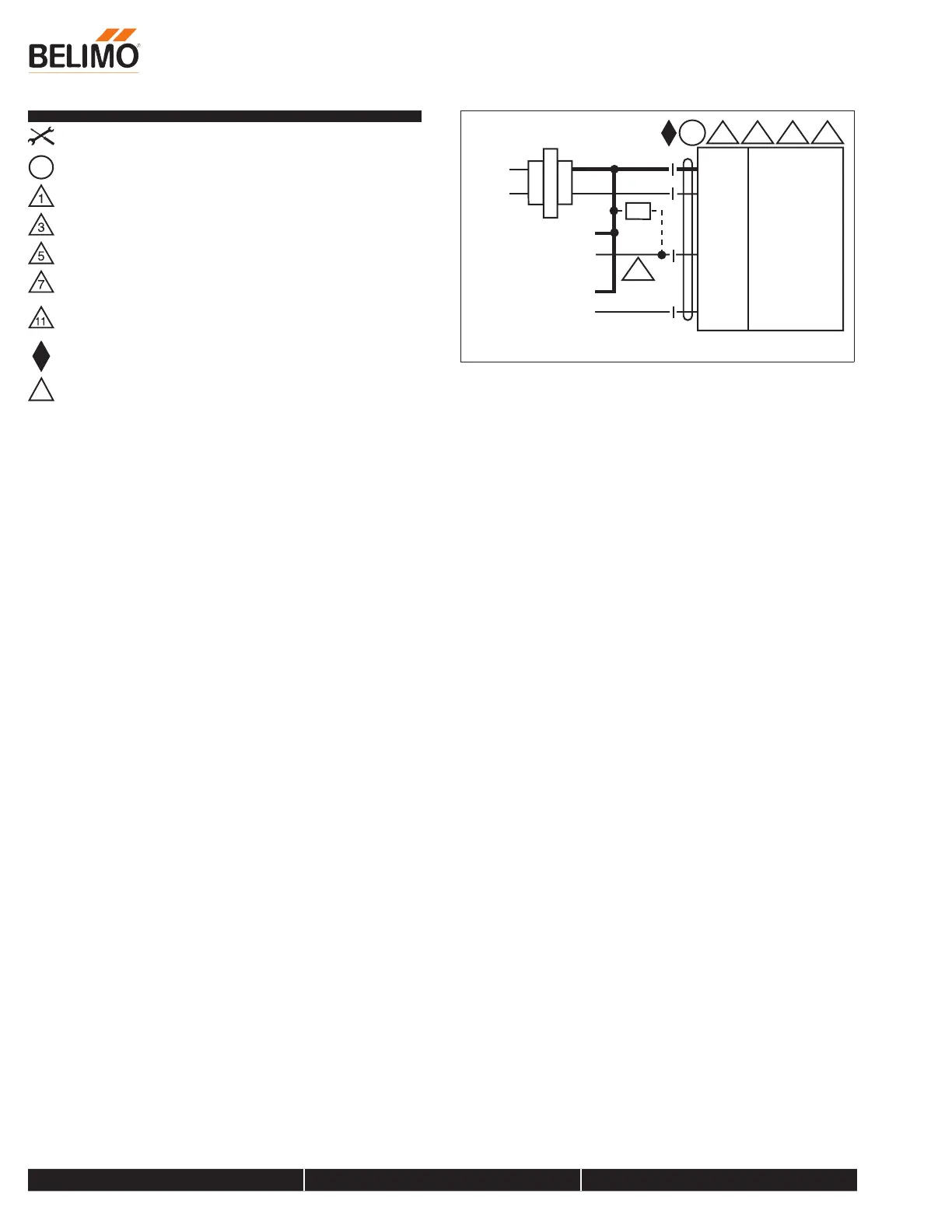
A
Actuators with appliance cables are numbered.
Provide overload protection and disconnect as required.
Actuators may also be powered by 24 VDC.
Only connect common to negative (-) leg of control circuits.
A 500 Ω resistor (ZG-R01) converts the 4 to 20 mA control signal to 2
to 10 VDC.
Actuators may be connected in parallel if not mechanically linked. Power
consumption and input impedance must be observed.
Meets cULus requirements without the need of an electrical ground
connection.
!
WARNING! LIVE ELECTRICAL COMPONENTS!
During installation, testing, servicing and troubleshooting of this
product, it may be necessary to work with live electrical components.
Have a qualified licensed electrician or other individual who has been
properly trained in handling live electrical components perform these
tasks. Failure to follow all electrical safety precautions when exposed to
live electrical components could result in death or serious injury.
Blk (1)
Red (2)
Wht (3)
Org (5)
24 VAC Transformer
Control Signal
(+)
VDC/mA
(–)
Feedback Signal
(+)
2 to 10 VDC
(–)
500
olts
A
1
3
5 11
Ω
Ω
Common
+ Hot
Y Input, 2 to 10 V
U Output
7
2 to 10 VDC / 4 to 20 mA Control
AFRB24-SR
Modulating, Spring Return, 24 VAC for 2 to 10 VDC or 4...20 mA Control Signal
800-543-9038 USA 866-805-7089 CANADA 203-791-8396 LATIN AMERICA / CARIBBEAN
Date created, 05/02/2019 - Subject to change. © Belimo Aircontrols (USA), Inc.