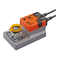
Technical data sheet SM24A-S
www.belimo.com SM24A-S • en-gb • 2022-07-18 • Subject to change 3 / 4
Mechanical accessories Description Type
Actuator arm for standard shaft clamp (reversible) AH-20
Shaft extension 240 mm Ø20 mm for damper shaft Ø 12...21 mm CrNi AV12-25-I
Shaft extension 240 mm Ø20 mm for damper shaft Ø 8...22.7 mm AV8-25
Ball joint suitable for damper crank arm KH8, Multipack 10 pcs. KG8
Ball joint suitable for damper crank arm KH8 / KH10, Multipack 10 pcs. KG10A
Damper crank arm Slot width 8.2 mm, clamping range Ø10...18 mm KH8
Shaft clamp one-sided, clamping range Ø8...26 mm, Multipack 20 pcs. K-ENSA
Shaft clamp one-sided, clamping range Ø12...26 mm, for CrNi shaft
(INOX), Multipack 20 pcs.
K-ENSA-I
Shaft clamp reversible, clamping range Ø10...20 mm K-SA
Anti-rotation mechanism 180 mm, Multipack 20 pcs. Z-ARS180
Anti-rotation mechanism 230 mm, Multipack 20 pcs. Z-ARS230
Form fit insert 10x10mm, Multipack 20 pcs. ZF10-NSA
Form fit insert 12x12mm, Multipack 20 pcs. ZF12-NSA
Form fit insert 15x15 mm, Multipack 20 pcs. ZF15-NSA
Form fit insert 16x16mm, Multipack 20 pcs. ZF16-NSA
Mounting kit for linkage operation for flat installation ZG-SMA
Position indicator, Multipack 20 pcs. Z-PI
Base plate extension for SM..A to SM../AM../SMD24R Z-SMA
Electrical installation
Supply from isolating transformer.
Parallel connection of other actuators possible. Observe the performance data.
Wiring diagrams
AC/DC 24 V, open/close AC/DC 24 V, 3-point
Cable colours:
1 = black
2 = red
3 = white
S1 = violet
S2 = red
S3 = white
Cable colours:
1 = black
2 = red
3 = white
S1 = violet
S2 = red
S3 = white
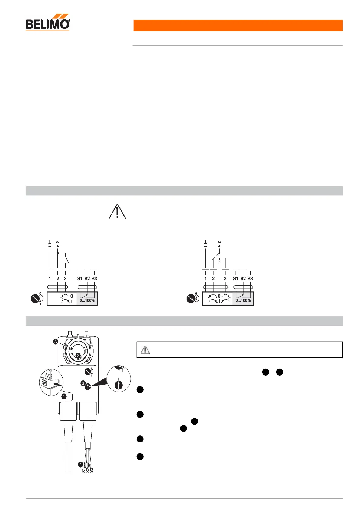
Operating controls and indicators
Auxiliary switch settings
Note: Perform settings on the actuator only in deenergised state.
For the auxiliary switch position settings, carry out points to successively.1 4
Manual override button
Holding button pressed down: Gear train disengages.
Manual override is possible.
Shaft clamp
Turn until edge line displays the desired switching position of the actuator and
release button .
Auxiliary switch
Turn rotary knob until the arrow points to the vertical line.
Cable
Connect continuity tester to S1 + S2 or to S1 + S3.
If the auxiliary switch should switch in the opposite direction, rotate the auxiliary switch
by 180°.
1
2
A
1
3
4