Page 2
Technical Solutions 2005/06
Function
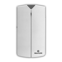
e BE1023 Bellman Visit Door Transmitter is a transmitter
within the Bellman Visit System for indoor use, which recognises
the sound emitted by a doorbell. If the doorbell is electromechanical,
the Door transmitter also detects the electromagnetic field emitted by
the doorbell.
Installation & connection
e unit is generally installed on a wall or door. It is mounted using
the factory-fitted, self-adhesive Velcro tape or with the wall bracket
and screw supplied.
For best results, the Bellman Visit Door Transmitter should be placed
as close as possible to, or just under, the left of the doorbell at a
maximum distance of 3 cm.
e unit is connected to the Bellman Visit System by radio.
For further information see Settings.
It is activated via the built-in microphone (4) and/or the built-in
magnetic coil.
Testing
To test the Bellman Visit Door Transmitter’s radio transmitter,
the Bellman Visit receiver must be tuned to the same channel
as the Door transmitter.
• Now press test button (2)
• e receiver will indicate whether there is an alarm from the
Bellman Visit Door Transmitter.
Testing the microphone:
• e microphone can be tested by ringing the doorbell.
• e Bellman Visit Door Transmitter will respond by lighting
the green LED (1).
Te
sting the magnetic coil:
• e magnetic coil can be tested by turning off the microphone
with switch 2 of the tone switch (5) (see Functions below).
• Ring the electromechanical doorbell positioned as set out in the
above instructions.
• e Bellman Visit Door Transmitter will respond by lighting
the green LED (1).
Bellman Visit Door Transmitter
BE1023
Technical information
Power supply
Battery: 9 V 6LR61 Alkaline
9 V 6F22 Lithium
Operating time:
6LR61 Alkaline: approximately 5 years
6F22 Lithium: approximately 10 years
Power consumption:
Active: 15 mA
Idle position: <0.1mA
Radio function
Radio frequency: 433.92 MHz
Number of channels: 64 logical channels
Coverage: e normal coverage between a
transmitter and receiver in the Bellman
Visit System is approximately 80 metres with
a clear line of sight. Coverage is reduced if
walls and large objects screen off the signal.
Any thick walls constructed of reinforced
concrete will greatly affect coverage.
Activation via
e in-built microphone and
in-built magnetic coil
Test button
Additional information
For indoor use only
Dimensions WxHxD: 80 x 145 x 36 mm
Weight: With battery: 210 g
Without battery: 160 g
Colour: White with a red triangle

